Iridium oxide electrode and its manufacturing method

A technology of iridium oxide electrode and iridium oxide, which is applied in the field of electrochemistry, can solve the problems of not mentioning the temperature range and poor reproducibility of iridium oxide electrode performance, and achieve the effects of high-efficiency, high-quality manufacturing, high sensitivity, and wide application

Inactive Publication Date: 2007-10-24
WUHAN UNIV
View PDF1 Cites 12 Cited by
  • Summary
  • Abstract
  • Description
  • Claims
  • Application Information

AI Technical Summary

Problems solved by technology

This method does not mention the pretreatment of the iridium electrode surface on the substrate and the temperature range of the activation process, both of which have a significant impact on the performance of the activated iridium oxide electrode
The published method also does not clearly describe the activation solution, resulting in poor reproducibility of the performance of the activated iridium oxide electrode

Method used


Image

  • Iridium oxide electrode and its manufacturing method
  • Iridium oxide electrode and its manufacturing method
  • Iridium oxide electrode and its manufacturing method

Examples


Embodiment 1

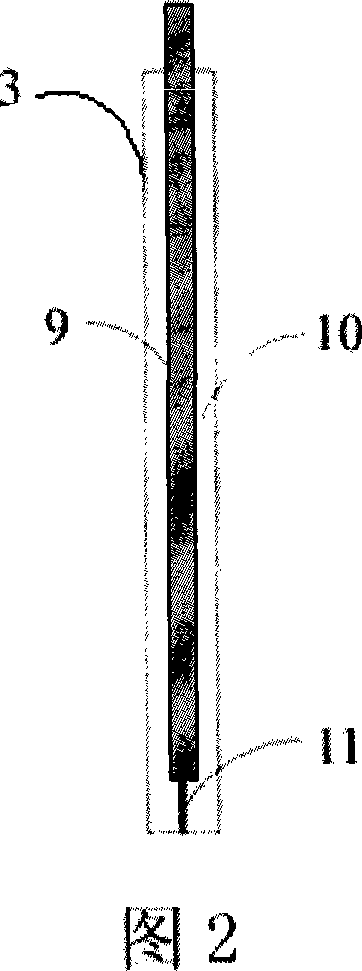
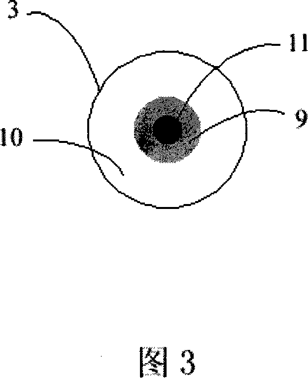
[0043]Embodiment 1: As shown in FIGS. 2 and 3 , it is an embodiment of the unipolar iridium oxide electrode with one electrode core 11 of the present invention. Described iridium oxide electrode, it has an insulating layer 10, wherein encapsulates an electrode core 11; Described electrode core 11 is a conductor that one end is in metal iridium, and its one end is connected with wire 9, and the surface layer of iridium oxide is exposed on the insulating layer 10 outside. The electrode core 11 is a conductor that is activated to generate an iridium oxide surface layer on the outer surface (or the outer surface) of one end of the metal iridium wire (a metal iridium sheet is another embodiment). The material of the insulating layer 10 is glass, and can also be selected as silicon rubber, or epoxy resin, or silicon dioxide, or ceramics.

Embodiment 2

[0044] Embodiment 2: As shown in FIGS. 4 and 5 , the difference from the above embodiments is an array type iridium oxide electrode with four electrode cores 11 .

Embodiment 3

[0045] Embodiment 3: Different from the above-mentioned embodiment, the electrode core 11 is a conductor whose one end is deposited on the outer surface of the non-iridium metal and then activated to generate the surface layer of iridium oxide on the bottom layer of metal iridium, and the non-iridium metal is preferably From titanium, platinum, or gold, or nickel, or silver, or copper, or iron, or alloys thereof may also be selected.

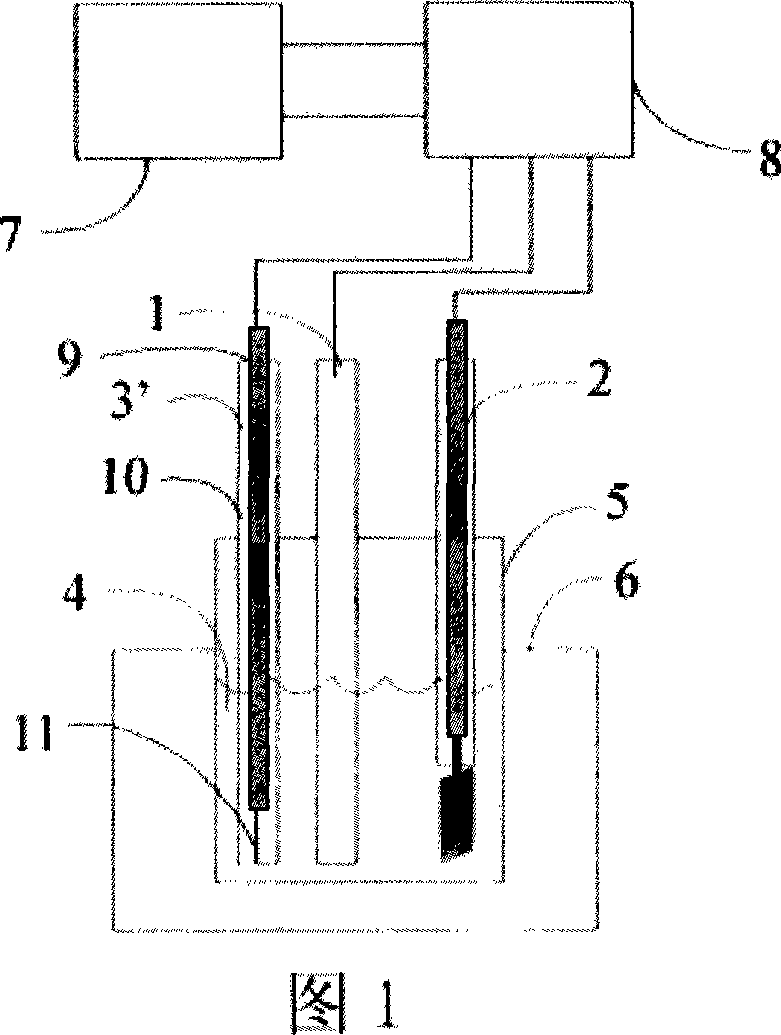
[0046] 2, the embodiment of the manufacture method of a kind of iridium oxide electrode of the present invention:

[0047] As shown in Figure 1, a kind of manufacture method of iridium oxide electrode of the present invention, it comprises the following steps:

[0048] A, the electrode core 11 that is not activated to generate the iridium oxide surface layer is connected to the wire 9, and is encapsulated in the insulating layer 10, and one end of the electrode core 11 is exposed outside the insulating layer 10, and becomes the electrode 3 ' to ...


PUM

PropertyMeasurementUnit
current densityaaaaaaaaaa

Abstract

The invention relates to an iridium oxide electrode and the method for preparing the same, belonging to the field of electrochemical technique. Said electrode is especially suitable for nerve electrographic recording and nerve electric stimulation and pH sensor. There is one insulating layer in the iridium oxide electrode, at least one electrode core is packed inside; at least one end of said electrode core is on the electric conductor, the outer surface of metallic iridium or non-iridium is deposited, and the electric conductor surface is regenerative iridium oxide. One end is connected with wire and the iridium oxide surface is out of insulating layer. The process of electrochemical activation to generate iridium oxide surface comprises following steps: a. pre-treating electrode; b. putting electrode into activating solution for treatment; c. depolarizing activation electrode through reference electrode and auxiliary electrode. The iridium oxide electrode is characterized by safety, reliability, high sensitivity, practical, wide application, fast, controllable and high efficient production method.

Description

technical field [0001] The invention relates to an iridium oxide electrode and a manufacturing method thereof, which uses an electrochemical method to activate the surface of the electrode, belongs to the field of electrochemical technology, and is especially suitable for nerve electrical recording and nerve micro-electric stimulation, and a pH sensor. Background technique [0002] There are many advantages in developing microelectrode arrays for miniaturized neural signal recording and neural tissue stimulation. First of all, it can reduce surgical trauma, thereby reducing tissue inflammatory response. Second, it is beneficial to selectively excite nerve fibers and neurons. Third, increase the resolution of recorded neurophysiological signals. The development of miniaturized microelectrode arrays is an important direction in the fields of brain-computer interface (BCI) and neural prostheses. Although microelectromechanical systems (MEMS) provide technical means for the f...

Claims


Application Information

Patent Timeline
Patent Type & Authority Applications(China)
IPC IPC(8): A61B5/04A61B5/05G01N27/30
CPCC25F1/00
Inventor 段晏文鲁艺曹余良蔡政旭杨汉西
Owner WUHAN UNIV
Why Eureka
Try Eureka