Diesel engine particle catcher

A particle trap and particle trap technology, applied in the direction of machines/engines, mechanical equipment, engine components, etc., can solve the problems of frequent regeneration, increased vehicle cost, failure, etc., to facilitate regeneration and maintenance, improve utilization efficiency, The effect of improving the service life

Inactive Publication Date: 2007-10-24
JILIN UNIV
View PDF0 Cites 10 Cited by
  • Summary
  • Abstract
  • Description
  • Claims
  • Application Information

AI Technical Summary

Problems solved by technology

However, a large number of particles contained in diesel exhaust emissions endanger human health and pollute the environment on which human beings live. For this reason, increasingly strict vehicle emission regulations have imposed stricter restrictions on them
At present, the measures of improving diesel quality and internal purification can no longer meet the requirements of more stringent emission regulations. Particulate capture technology as an external purification has become the most effective measure to reduce diesel particulate emissions and has the best commercial prospects. Technology
However, the diameters of the particles emitted by diesel engines have a wide range of distributions, and particles of different diameters have different effects on human health. It is difficult for a particle filter with a single pore size to capture different particle sizes, resulting in low capture efficiency of the particle filter , Short service life and frequent regeneration times make the diesel engine have to install an additional regeneration device
However, the limited vehicle layout space and on-board energy make it difficult for the volume and power of the regenerative device to reach the ideal state, resulting in incomplete regeneration, frequent regenerations, and aging and failure of the filter element of the particulate filter; in addition, the on-board regenerative device not only It consumes on-board energy, increases the cost of the vehicle, and also causes a waste of resources

Method used


Image

  • Diesel engine particle catcher
  • Diesel engine particle catcher
  • Diesel engine particle catcher

Examples


Embodiment Construction

[0019] The specific content of the present invention will be further described below in conjunction with the embodiments shown in the accompanying drawings.

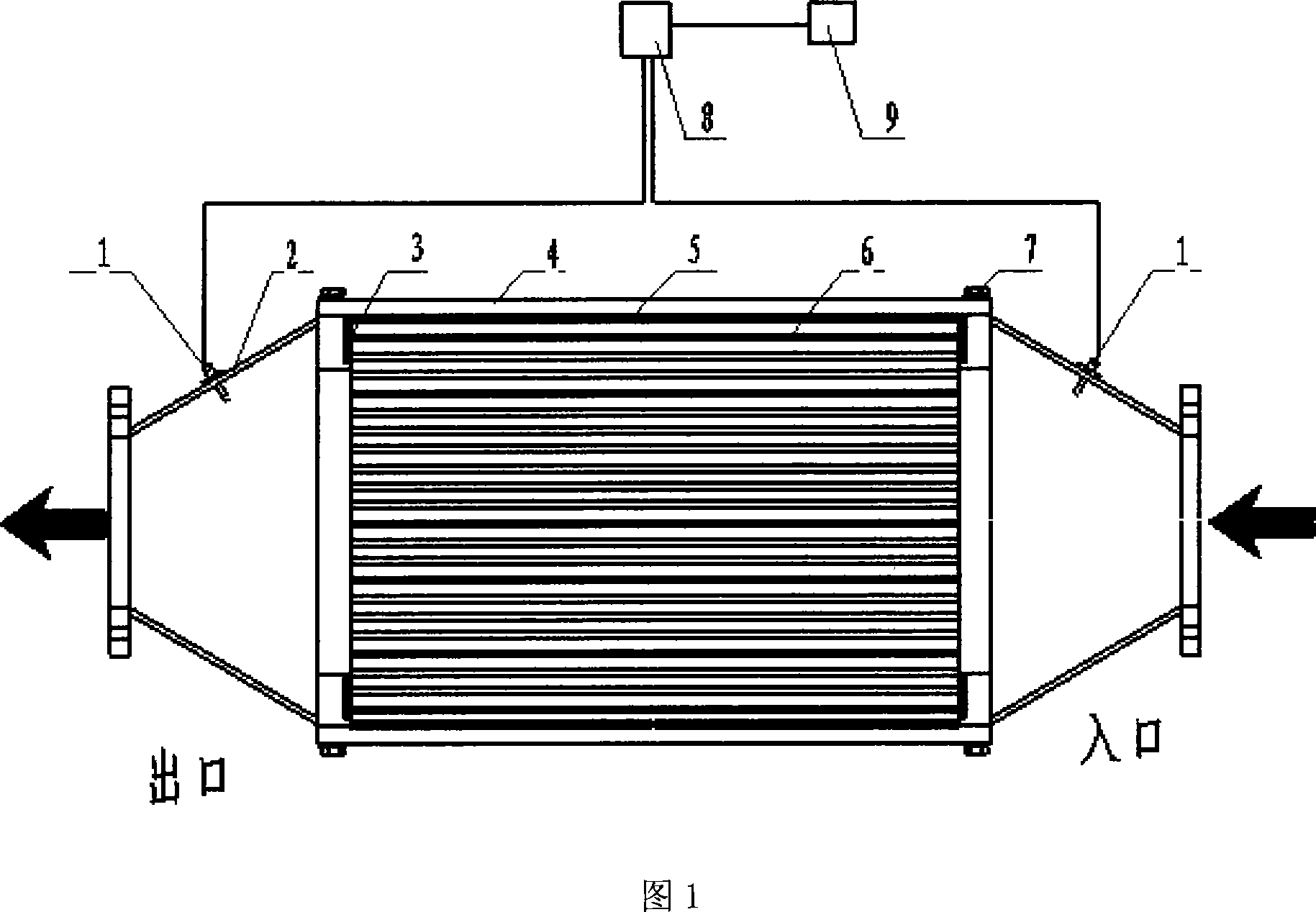
[0020] Fig. 1 is a schematic diagram of a single structure of a square graded filtration, detachable, off-vehicle cycle regeneration diesel engine particulate filter. The exhaust gas of the diesel engine enters the particulate filter from the inlet, and the filter element 6 filters and captures the particulates in the exhaust gas. 5. It is used to prevent the leakage of exhaust gas, and at the same time, it can start the function of shock absorption. During the installation process, the pressure plate 4 in the middle of the shell is pre-tightened and anti-loosening, which can avoid the leakage between the pressure plate and the filler due to poor fit. phenomenon, the positioning surface 3 is used on the housing to prevent exhaust gas leakage caused by the movement of the filter element 6, the pressure sensor 1 collects th...


PUM


Abstract

The present invention involves the post-processor technology of diesel engine, particularly relates to a detachable diesel engine particle drip catcher. It consists of shell, filter element, pressure sensor, control unit and display device. Said shell uses separated shell and bolts (7) precompact connection, the filter element (6) is removable, filling materials are filled between the middle press plate (4)of shell and filter element (6), the partitioned particle drip catcher shell is divided into shell (2) and filter element (6) which are filled with filling materials between them, the two ends (2) of shell are tail gas input and output mouth, pressure sensor (1) is installed on the two ends of shell and connected with control unit (8), display device (9) is connected on the control unit (8). The invention aims at particle in different diameters in diesel engine, staged-filters and traps in order to improve the filtering effect, reduce trap device blocking up, prolong its regeneration cycle and retarding aging speed of filter elements, it improves the use life of particulate trap device.

Description

technical field [0001] The invention relates to the technical field of post-processors of diesel engines, in particular to a detachable diesel engine particulate trap. technical background [0002] Diesel engines are widely used in various fields of the national economy due to their high thermal efficiency, good fuel economy, large low-speed torque, long service life and low maintenance costs. However, a large number of particulates contained in diesel exhaust emissions endanger human health and pollute the environment on which human beings live. Therefore, increasingly strict vehicle emission regulations have imposed stricter restrictions on them. At present, the measures of improving diesel quality and internal purification can no longer meet the requirements of more stringent emission regulations. Particulate capture technology as an external purification has become the most effective measure to reduce diesel particulate emissions and has the best commercial prospects. T...

Claims


Application Information

Patent Timeline
Patent Type & Authority Applications(China)
IPC IPC(8): F01N3/023F01N9/00
CPCY02T10/47Y02T10/40
Inventor 李君张辉高莹朱昌吉杨世春邓宝清王立军
Owner JILIN UNIV
Why Eureka
Try Eureka