Movable type hydraulic pumping station

A hydraulic pump station, mobile technology, applied in the direction of fluid pressure actuation device, accumulator device, etc., can solve the problems of mobile hydraulic pump station, such as dirt, malfunction, labor and time, etc., to achieve structural Compact, guaranteed clean and easy to use

Inactive Publication Date: 2007-10-24
侯学礼
View PDF0 Cites 6 Cited by
  • Summary
  • Abstract
  • Description
  • Claims
  • Application Information

AI Technical Summary

Problems solved by technology

Every time the hydraulic pump station is used, the hydraulic working device must be docked with the hydraulic output port through the hydraulic hose, which is labor-intensive and time-consuming, and it is inconvenient to use. Dirty or oil leakage cannot work normally

Method used


Image

  • Movable type hydraulic pumping station
  • Movable type hydraulic pumping station
  • Movable type hydraulic pumping station

Examples


Embodiment 1

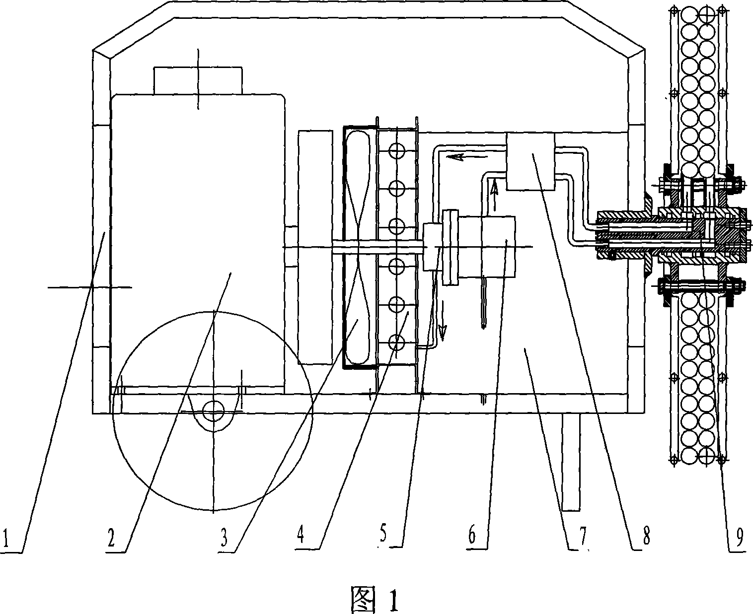
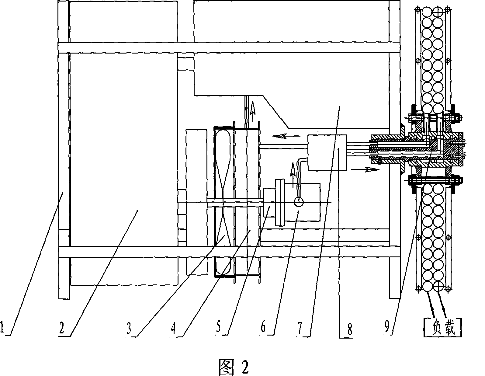
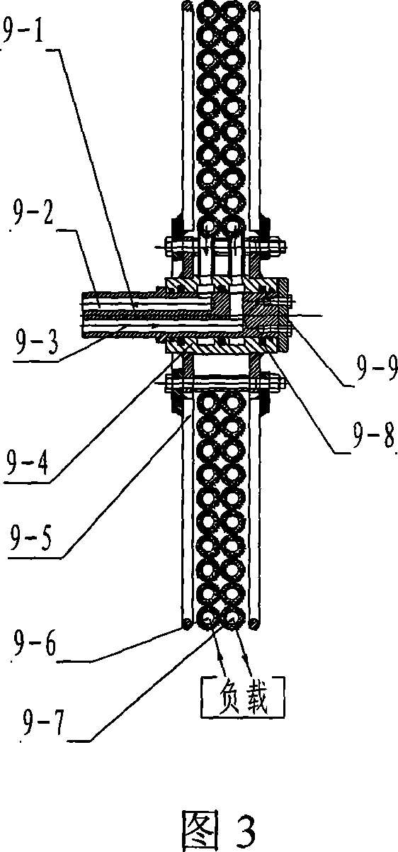
[0018] Embodiment 1: In the figure, 1. vehicle frame; 2. power machine; 3. fan; 4. radiator; 5. coupling; 6. oil pump; 7. fuel tank; 8. hydraulic control valve; 9. pipe winder; 9-1, mandrel; 9-2, oil outlet hole; 9-3, oil inlet hole; 9-4 mandrel jacket; 9-5, coiling frame; 9-6, oil return pipe; 9-7, inlet Oil pipe; 9-8, sealing ring; 9-9, jacket baffle; 9-10, elastic circlip.

[0019] In Fig. 1, Fig. 2 and Fig. 3, the hydraulic pump station has vehicle frame 1, power machine 2, oil tank 7, fan 3, radiator 4, coupling 5, oil pump 6, hydraulic control valve 8, load and A pipe winder 9, a power machine 2, an oil tank 7, a fan 3, a radiator 4, a coupling 5, an oil pump 6, are installed in the vehicle frame 1, load And hydraulic control valve 8, described power machine is a diesel engine, fuel tank, oil pump, hydraulic control valve, pipe winder, load The radiator is connected sequentially through pipelines; the shaft at one end of the coupling is connected to the diesel engine...

Embodiment 2

[0023] Embodiment 2: In Fig. 4, there are independent oil inlet holes and oil outlet holes on the mandrel, the oil inlet holes and the oil outlet holes have axial holes and radial holes, and the axial holes communicate with the radial holes, There is an oil groove and a sealing ring groove on the mandrel, the position of the radial hole corresponds to the oil groove on the mandrel, and an axial limiter is connected to the mandrel, and the axial limiter is a circlip 9-10; The position of the overcoat radial hole on the mandrel overcoat corresponds to the oil groove on the mandrel.

[0024] Others are the same as in Embodiment 1, omitted.

Embodiment 3

[0025] Embodiment 3: In Figure 5, the pipe winder is connected with a pipe winding frame on the outside of the mandrel, and there are independent oil inlet holes and oil outlet holes on the mandrel, and the oil inlet holes and oil outlet holes have axial holes And the radial hole, the axial hole is connected with the radial hole, and the position of the radial hole corresponds to the oil groove inside the mandrel jacket; there are oil grooves and sealing ring grooves on the inner wall of the mandrel jacket, and there are Outer jacket radial hole, the outer jacket radial hole is an oil inlet hole and an oil outlet hole, the position of the outer jacket radial hole is corresponding to the oil groove on the mandrel jacket, and the mandrel jacket is a fixed body.

[0026] Others are the same as in Embodiment 1, omitted.


PUM


Abstract

A mobile hydraulic pump station belongs to hydraulic pump station. The hydraulic pump station consists of car frame, power machine, fuel tank, fan, radiator, junction box, oil pump, hydraulic pressure control valve and tube-bound device; the car frame is equipped with diesel engine, fuel tank, fan, radiator, junction box, oil pump, hydraulic pressure control valve, the fuel tank, oil pump, hydraulic pressure control valves, tube-bound device and radiator are sequentially connected through pipelines; the axle of junction box one end is connected with diesel engine and another end is connected with oil pump, the tube-bound device is installed on the car frame, and hydraulic port of tube-bound device is connected with hydraulic pressure control valve through pipelines; the tube-bound device consists of mandrel, mandrel outer sleeve and tube-bound frame, the mandrel outer sleeve is nested on the mandrel, and sealing ring is installed between the mandrel and the mandrel outer sleeve; the tube-bound frame is installed on the outer end of tube-bound device. The hydraulic pump station has compact structure and volume, only is the hydraulic rubber hose with work device pulled out from tube-bound device when works, inactive and repetitive operation is not needed, it saves labor and time, the use is easy, it ensures the cleanliness of hydraulic oil effectively and saves use cost significantly .

Description

technical field [0001] The invention relates to a hydraulic pump station, in particular to a mobile hydraulic pump station. Background technique [0002] At present, the mobile hydraulic pump station used by people has a frame and a power machine. The power machine is a diesel engine or a gasoline engine or an electric motor, a radiator, a blower, a fuel tank, a coupling shaft, an oil pump, a hydraulic control valve and a load. Diesel engines, Radiator, blower, oil tank, coupling shaft, oil pump and hydraulic control valve, the hydraulic control valve is connected to the hydraulic output port, the coupling shaft is connected to the diesel engine, and connected to the oil pump through the blower, the radiator is located on the air outlet of the blower, on the rack A hydraulic output port is connected to the hydraulic control valve, and a pressure gauge is connected to the hydraulic control valve. Every time the hydraulic pump station is used, t...

Claims


Application Information

Patent Timeline
Patent Type & Authority Applications(China)
IPC IPC(8): F15B1/00
Inventor 侯学礼
Owner 侯学礼
Why Eureka
Try Eureka