Plastic ball valve

A plastic ball valve and plastic valve technology, applied in the field of plastic ball valves, can solve the problems of increased motion friction, large valve ball holding force, difficult valve core rotation, etc., and achieve the effect of reducing the contact area and reducing the motion friction.

Inactive Publication Date: 2007-10-24
罗荣森
View PDF3 Cites 1 Cited by
  • Summary
  • Abstract
  • Description
  • Claims
  • Application Information

AI Technical Summary

Problems solved by technology

However, the defect of this scheme is also a technical problem that has puzzled the plastic ball valve industry for a long time, that is, the problem that the plastic valve body has too much grip on the valve ball (correspondingly, the friction force is too large when the relative movement between the two is caused)
Careful analysis shows that the above-mentioned problem of excessive holding force of the plastic valve body on the valve ball is due to the following two reasons: ①. In this plastic ball valve, there is no separate setting that is compatible with the spherical surface of the valve ball and forms a seal. The auxiliary ball seat, when the ball valve is in the closed state, completely depends on the inner wall of the plastic valve body and the surface compatible with the valve ball of the integrated valve core to form a sealing pair with the outer surface of the valve ball, which requires When injecting molds and injection molding valve bodies, it is necessary to make the inner surface of the molded plastic valve fit closely with the outer surface of the valve ball, and this tight fit is a kind of tight fit between the inner surface of the valve and the outer surface of the valve ball. Large-area tight fit, not the ring fit required by the usual ring-shaped sealing pair (for the ball valve, it only needs to form a ring-shaped sealing pair when it is closed)
Corresponding to the above-mentioned large-area tight fit, the kinetic friction between the valve body and the valve ball increases significantly and unnecessarily, resulting in difficulty in the rotation of the valve core
②. When the plastic valve body is made by hot-melt injection molding, in order to realize the large-area close fit between the inner surface of the valve and the outer surface of the valve ball and form a sealing pair, it is necessary to make the valve body being injection-molded The inner wall of the valve body and the outer surface of the valve ball are in a bonded state. However, after the hot-melt injection molding is completed, the molded plastic valve body will shrink to a certain extent due to gradual cooling, and this shrinkage will increase the force between the valve body and the valve core. Clamping force, and correspondingly further increase the friction between the inner cavity of the plastic valve body and the outer surface of the valve ball, making the opening and closing of the ball valve more inconvenient, and even the integrated valve core is extremely difficult to rotate.
But, on the basis of this assumption, the following defects still occur in this plastic ball valve: 1., because the aperture at the place where its body is connected to the bonnet and the through hole where the valve stem passes through the body are relatively large (as mentioned above, this is for the convenience of Put the connected valve stem and valve core into the body), the large through hole on the body has a large part of the redundant space that needs to be filled, which causes the waste of materials when manufacturing the valve body, and at the same time, it is different from the existing Compared with other ball valves with the same nominal diameter (DN), the above-mentioned oversized through hole will also make the shape of the valve body too large, which will cause inconvenience in installation and narrow application range.
②. In this product, the body and the two bonnets are threaded. Due to the creep property of plastic materials, when the body and the two bonnets are made of plastic materials, the connection between the body and the two bonnets The threaded connection will naturally loosen during long-term use, so that the three-piece split valve body will leak (from this point of view, this product is not suitable for making plastic ball valves)

Method used


Image

  • Plastic ball valve
  • Plastic ball valve
  • Plastic ball valve

Examples


Embodiment 1

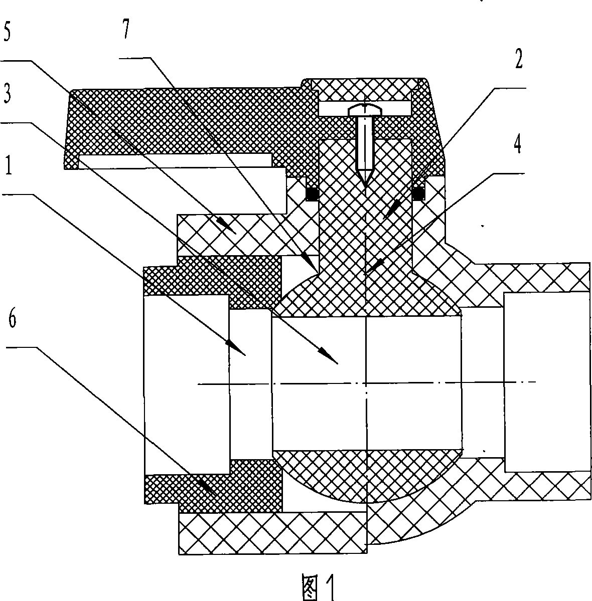
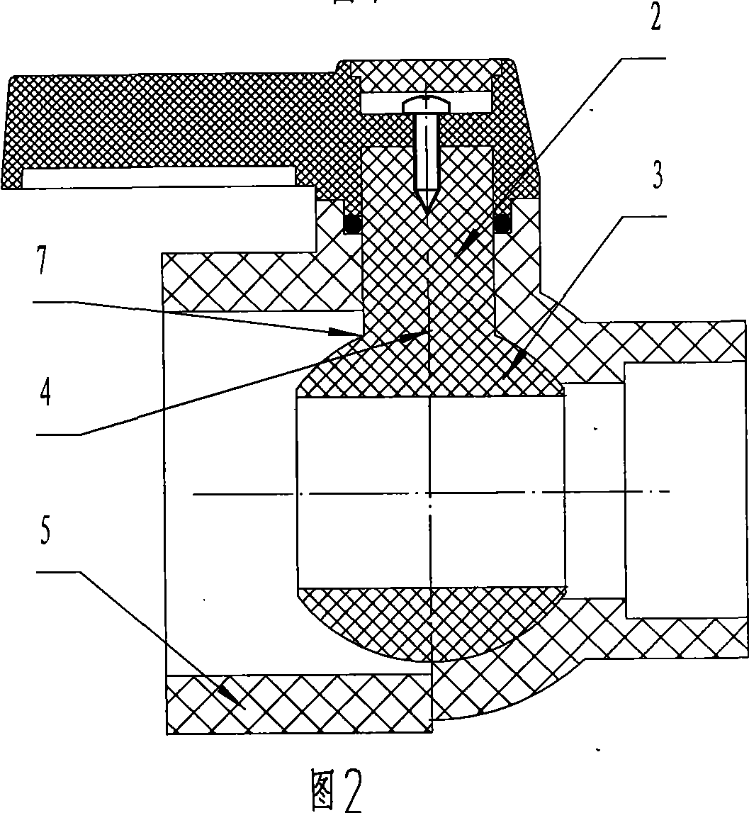
[0062] Embodiment 1: As shown in Figures 1-2, the plastic ball valve of this embodiment includes a valve body with a flow channel inside, a valve ball seat 1, and an integrated valve core 4 in which the valve stem 2 and the valve ball 3 are pre-connected as one. The valve ball 3 of the integrated spool is located in the valve body, the valve stem 2 of the integrated spool passes through the valve body, and the valve ball seat 1 is compatible with the valve ball 3 of the integrated spool, which is characterized in that : the valve body is a plastic valve body 5, and is provided with a plastic valve cover 6 with a through hole, the plastic valve cover 6 is bonded to the plastic valve body 5, and the through hole of the plastic valve cover 6 is bonded to the plastic valve cover 6 The flow passages in the valve body 5 are connected.

[0063] In this embodiment, the bonding between the plastic valve cover 6 and the plastic valve body 5 is hot-melt socket bonding.

[0064] The valv...

Embodiment 2

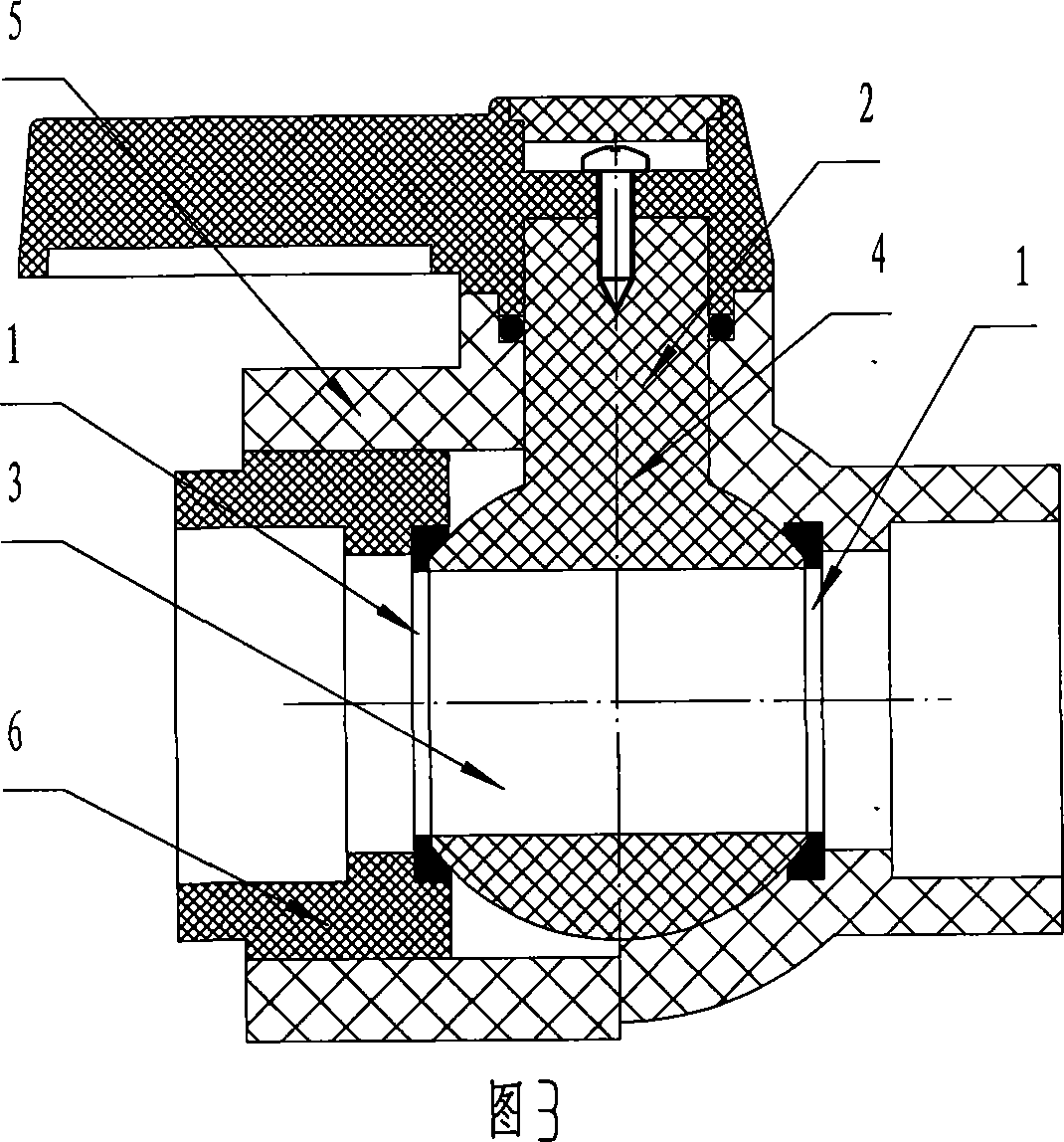
[0065] Embodiment 2: As shown in Figures 3-4, this embodiment is similar to Embodiment 1, the difference is that the plastic valve cover 6 has an annular sealing surface adapted to the spherical surface of the valve ball 3 of the integrated valve core , the annular sealing surface and the spherical surface of the valve ball 3 of the integrated valve core form a sealing pair. The annular sealing surface in this embodiment itself acts as a valve ball seat 1, that is, the annular sealing surface is a valve ball seat 1 provided separately, and there are two valve ball seats 1, and the two valve ball seats 1 are respectively provided On both sides of the valve ball 3 of the integrated valve core, in this embodiment, one of the valve ball seats 1 is located on the plastic valve cover 6 .

[0066] The plastic valve body 5 in this embodiment is a plastic valve body made of polyethylene material.

Embodiment 3

[0067] Embodiment 3: As shown in FIGS. 5-6 , this embodiment is similar to Embodiment 2, except that the valve ball seat 1 is one, and the valve ball seat 1 is located on the plastic valve cover 6 .


PUM


Abstract

The present invention relates to a ball valve, particularly a plastic ball valve. The ball valve includes valve body within flow passage, valve seat and integrated spool which pre-connects the valve bar and the valve ball into one unit, the valve ball of said integrated spool is installed in the valve body, the valve bar of said integrated spool passes through the valve body, said valve ball seat is matched with the valve ball of integrated spool, it is characterized by: said valve body is plastic valve body and is equipped with one or two plastic valve covers with through-hole, said plastic valve covers are bonded with the plastic valve body, the through-hole of said plastic valve cover is connected with the flow passage in plastic valve body. The product can make the rotation of valve ball in plastic ball valve more flexible, and make the ball valve products has longer use life and thus has highly practical value.

Description

technical field [0001] The invention relates to a ball valve, in particular to a plastic ball valve. Background technique [0002] Existing plastic ball valves are generally manufactured by one of the following schemes: [0003] (A), as disclosed in the Chinese invention application No. 03153661.1, is a buried polyethylene plastic ball valve and its packaging method. The plastic ball valve adopts a split structure of the valve ball and the valve stem. In this way, after the parts are formed, the valve stem and the valve stem are separated The valve balls are respectively put into the valve body for assembly. This technology is one of the commonly used and feasible schemes for the production of existing plastic ball valves. However, the defects of this scheme are also obvious, that is, during the long-term use of such ball valves, due to the The strength of commonly used plastic materials such as ethylene is inherently low, and it is easy to cause the gap between the valve ...

Claims


Application Information

Patent Timeline
Patent Type & Authority Applications(China)
IPC IPC(8): F16K5/06F16K27/06
Inventor 罗荣尧罗荣森
Owner 罗荣森
Why Eureka
Try Eureka