Synchronous reflection distribution photometer

A goniophotometer and synchronous reflection technology, which is applied in photometry, optical radiation measurement, and optical performance testing, etc., can solve the problems of occupying darkroom space, large space occupied by the darkroom, and complicated adjustment, so as to achieve convenient optical path and convenient installation , easy to adjust the effect

Active Publication Date: 2007-10-24
HANGZHOU EVERFINE PHOTO E INFO
View PDF0 Cites 4 Cited by
  • Summary
  • Abstract
  • Description
  • Claims
  • Application Information

AI Technical Summary

Problems solved by technology

Although these two schemes are more accurate light intensity distribution measurement schemes at present, they have their own defects.
First of all, they all have the same problem: the darkroom takes up a lot of space
When the required measurement arm length (measurement distance) is large, it often takes up a considerable length of darkroom space, and the cost of implementing the test is very high.
In addition, as far as the central rotating mirror goniophotometer is concerned, the light source under test must move within a relatively large space range. Due to the inevitable existence of airflow, movement speed, acceleration and centrifugal force, it is difficult to ensure its high temperature when the light source under test is ignited. Steady state, this is a principle problem that cannot be overcome by this scheme; as far as the circular motion mirror goniophotometer is concerned, its measured light source is in a relatively static state, and can be ignited according to the natural position of the light source, and the light source is the most stable. However, in the existing method, the optical axis of the measured beam received by the horizontally placed optical receiver facing the light source under test will cause measurement errors due to oblique incidence to the optical receiver, and in order to receive the reflector in the entire circular motion The reflected light requires the optical receiver to have a larger receiving aperture, which will allow more stray light to enter the optical receiver, thereby affecting the test accuracy. In addition, when testing light sources of different sizes and beam angles, different The measurement is carried out under the measurement arm length (measurement distance), and when adjusting the measurement distance of the circular motion mirror goniophotometer, not only the position of the optical receiver is required to be adjusted, but also the angle of the receiving aperture and the reflection mirror is required to be adjusted, so that the entire measurement arm Long (measuring distance) adjustment is quite complicated, and it takes up a lot of space in the darkroom at a long measuring distance

Method used


Image

  • Synchronous reflection distribution photometer
  • Synchronous reflection distribution photometer
  • Synchronous reflection distribution photometer

Examples


Embodiment 1

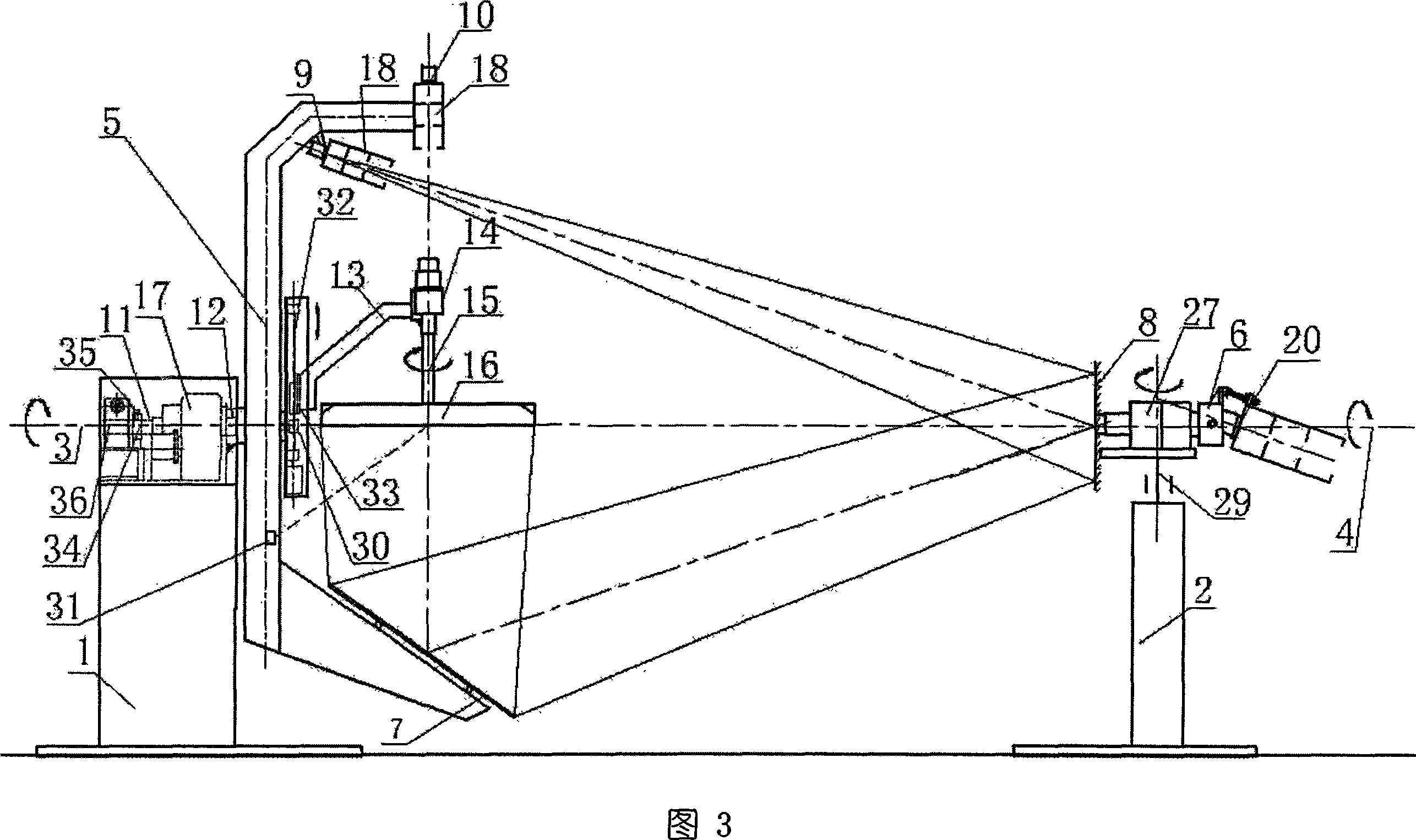
[0052]As shown in FIG. 3 , a fixed second optical mirror 8 perpendicular to the second centerline 4, a third optical receiver 20 that can rotate synchronously with the first optical mirror 7 and two optical receivers are set on the second base 2. Or switching mechanism 29. The third optical receiver 20 is connected with the second base 2 through the second rotating arm 6, and the second rotating arm 6 is driven by a drive motor 27 with a harmonic reducer, and the drive motor 27 can realize the first step through coding and automatic control. The second rotating arm 6 rotates synchronously with the first rotating arm 5 on the first base 1, and the optical axis of the third optical receiver 20 intersects with the horizontal rotation center line of the second rotating arm 6 and forms a certain angle. state, the horizontal rotation centerline of the second rotating arm 6 coincides with the first rotation centerline 3, and the third optical receiver 20 is just aligned with the firs...

Embodiment 2

[0058] As shown in FIG. 4 , the composition and structure on the second base of Embodiment 2 are the same as those of Embodiment 1 shown in FIG. 3 .

[0059] The first rotating arm 5 is a hollow cavity structure, the first optical reflector 7 is installed at one end of its outer side, the third optical reflector 21 is installed at the light entrance of the other end, and the first optical receiver 9 is arranged on the first The corresponding position in the rotating arm 5 adjusts the first optical reflector 7, the position of the third optical reflector 21 and the first optical receiver 9, so that the light bundle of the measured light source 16 passes through the first optical reflector 7 that is rotated, Normal incident fixed second optical reflector 8, after being reflected by the second optical reflector 8, just incident to the third optical reflector 21 that rotates synchronously with the first optical reflector 7, and then incident to the synchronous first optical receive...

Embodiment 3

[0063] As shown in FIG. 5 , the composition and structure of Embodiment 3 on the second base are the same as those of Embodiment 1 shown in FIG. 3 .

[0064] The first rotating arm 5 is a truss structure, as shown in Figure 6, the first optical reflector 7 is installed at its one end, the third optical reflector 21 is installed at the other end, the first optical receiver 9 and other several follow-up optical reflectors The mirror 23 is mounted at a corresponding position inside the first rotating arm 5 . Adjust the first optical reflector 7, the third optical reflector 21, the positions of other several follow-up optical reflectors 23 and the first optical receiver 9 so that the light bundle of the measured light source 16 passes through the rotating first optical reflector 7, just The incident fixed second optical reflector 8, after the second optical reflector 8 and the third optical reflector 21, is incident to the synchronously rotating first optical receiver 9 through se...


PUM


Abstract

The invention discloses a synchronous reflective distribution photometer, comprising two independent bases, wherein a first pivoted arm is connected with the first base to rotate around a first rotary central line, a first optical mirror is mounted on the first pivoted arm, a second optical mirror is connected with the second base or a second pivoted arm connected with the second base, the second pivoted arm can synchronously rotate coaxially with the first pivoted arm, an optical receiver is mounted on the pivoted arm, an object light source via a lamp arm is connected with the first base to rotate around itself shaft. The invention utilizes synchronous reflection and receiving, to effectively utilize the space of dark room, reduce measurement error, while the invention arranges optical receiver at different positions to select measuring arm length easily, which effectively resolve the defects of prior arm as large area of dark room, high measuring error, and hard range adjustment or the like.

Description

technical field [0001] The invention relates to a light radiation measuring instrument, which is mainly used for the light intensity distribution or light distribution performance test of various light sources and lamps in various directions, and a synchronous reflection goniophotometer for testing the total luminous flux of light sources and lamps. Background technique [0002] The distribution of light intensity in all directions in space is an important parameter of light sources and lamps. A goniophotometer is an instrument that accurately measures the distribution of light intensity of light sources and lamps with angles. The existing large mirror goniophotometer usually has two schemes, one is the center rotating mirror goniophotometer, as shown in Figure 1, the optical mirror of this kind of scheme is at the center of rotation during measurement. , while the measured light source moves on the circle around the center of rotation of the optical mirror; the other is a c...

Claims


Application Information

Patent Timeline
Patent Type & Authority Applications(China)
IPC IPC(8): G01J1/04G01M11/02
Inventor 潘建根
Owner HANGZHOU EVERFINE PHOTO E INFO
Why Eureka
Try Eureka