Binary photon sieve
A technology of photon sieve and light-transmitting film, applied in optics, optical components, instruments, etc., can solve the problem of low diffraction efficiency, achieve high diffraction efficiency, suppress high-order diffraction, and improve imaging contrast
- Summary
- Abstract
- Description
- Claims
- Application Information
AI Technical Summary
Problems solved by technology
Method used
Image
Examples
Embodiment 1
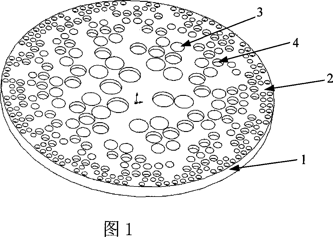
[0037] Figure 1 is an example of a binary photon sieve. The design parameters of this binary photon sieve are: photon sieve diameter Φ=80mm, F # =8, the base material is K9 glass, the thickness is a glass sheet of 2mm, and the design wavelength is 532nm; after calculation, this binary photon sieve has 2347 annular band cycles (composed of planar light-transmitting small holes and groove-type light-transmitting small hole composition), to obtain the distribution of the planar light-transmitting holes and the groove-type light-transmitting holes of the binary photon sieve; make the first mask according to the distribution of the planar light-transmitting holes; The distribution of the holes creates a second mask with alignment marks between the two masks. The first step is to vapor-deposit a layer of chromium film on the glass substrate, then apply glue on the surface coated with chromium film, use the first mask to photolithography, develop and fix, and use a solution to remov...
Embodiment 2
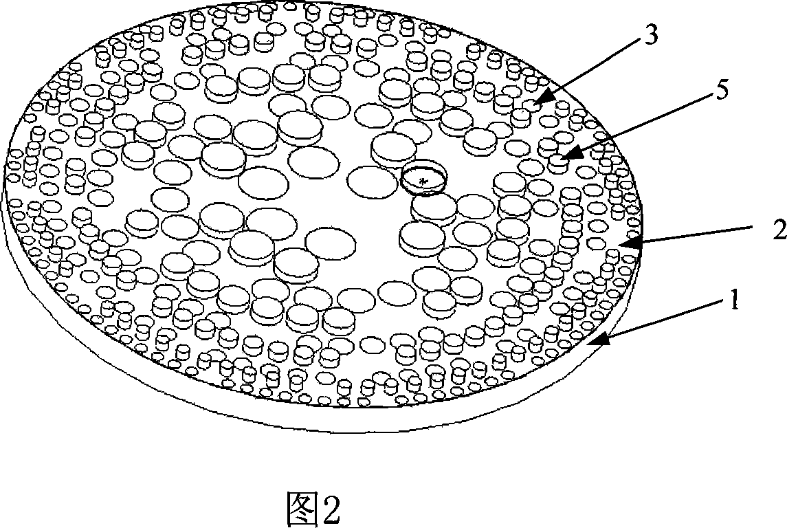
[0039] Figure 2 is an example of a binary photon sieve. The design parameters of this binary photon sieve are: photon sieve diameter Φ=80mm, F # =10, the base material is K9 glass, the thickness is a glass sheet of 2mm, and the design wavelength is 532nm; after calculation, this binary photon sieve has 1878 annular zone periods (composed of planar light-transmitting small holes and boss-type light-transmitting small holes Composition), to obtain the distribution of the planar light-transmitting holes and the convex platform-type light-transmitting holes of the binary photon sieve; make the first mask according to the distribution of the planar light-transmitting holes, and make the first mask according to the distribution of the convex-table light-transmitting holes A second mask is made with alignment marks between the two masks. The first step is to apply glue on the glass substrate. The thickness of the glue layer should be greater than 0.5 microns. Use the second mask to ...
PUM
 Abstract
Description
Claims
Application Information
 - R&D
- Intellectual Property
- Life Sciences
- Materials
- Tech Scout
- Unparalleled Data Quality
- Higher Quality Content
- 60% Fewer Hallucinations
Browse by: Latest US Patents, China's latest patents, Technical Efficacy Thesaurus, Application Domain, Technology Topic, Popular Technical Reports.
© 2025 PatSnap. All rights reserved.Legal|Privacy policy|Modern Slavery Act Transparency Statement|Sitemap|About US| Contact US: help@patsnap.com


