Automatic shift current mirror

A technology of automatic shifting and current mirror, applied in the field of current mirror, which can solve the problems of large error, limited output current adjustment range, poor uniformity, etc.

Inactive Publication Date: 2007-10-24
SILICON TOUCH TECH INC
View PDF0 Cites 7 Cited by
  • Summary
  • Abstract
  • Description
  • Claims
  • Application Information

AI Technical Summary

Problems solved by technology

However, the smaller the bias current, the larger the error still exists
[0007] In applications that require high current accuracy, the aforementioned error problem is very critical. For example, the LED/OLED drive circuit provides multiple output currents. Under low current operation, the error between the input current and the output current and the multi-channel output The current uniformity (skew) is obviously worse than that...

Method used


Image

  • Automatic shift current mirror
  • Automatic shift current mirror
  • Automatic shift current mirror

Examples


Embodiment Construction

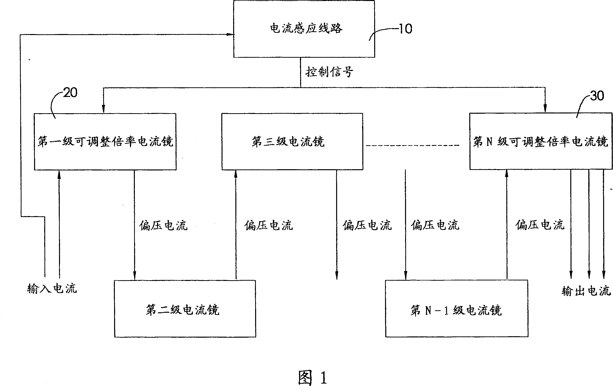
[0037] The invention provides a current mirror connected in series with more than two stages, by adjusting the magnification of the front and rear two-stage current mirrors, the bias current is changed to reduce the error, just like the shifting of the mechanical gear ratio, so it is called automatic Shift current mirror.

[0038] Please refer to Figure 1, the circuit architecture of the present invention mainly includes:

[0039] A pre-stage adjustable magnification current mirror 20, which establishes a bias current according to an input current;

[0040] A rear-stage adjustable-magnification current mirror 30 can be directly connected in series with the previous-stage adjustable-magnification current mirror 20, or any number of various intermediate-level current mirrors can be connected in series between the two. When there is an intermediate-level current mirror , each intermediate stage current mirror can have a plurality of output currents and a plurality of subsequent ...


PUM


Abstract

The invention relates to a current mirror with automatic shift, composed of a current sensitive circuit serially connected with a current mirror with multistage adjustable magnification, wherein the circuit detects the input current of the current mirror at one stage to be compared with a preset convert point, when the compared result meets switch condition, the circuit outputs a switch signal to the current mirror of each stage to adjust the magnification of each stage, thereby improving bias current and improve the uniformity of output current.

Description

technical field [0001] The invention relates to a current mirror, in particular to a current mirror which can automatically switch bias current and magnification to reduce errors. Background technique [0002] For a conventional current mirror composed of MOS devices (Metal Oxide Semiconductor Field Effect Transistor), the accuracy between the bias current and the output current will vary with the bias current. [0003] The MOS components in the current mirror usually operate in the saturation region, and the MOS source current in the simple saturation region (I ds ) relative to the gate voltage (V gs ) can be expressed by the following equation: [0004] I ds =[μC ox (W / L)(V gs -V th ) 2 ] / 2 [0005] Due to the process relationship, for different MOS components, μ and C in the above formula ox , W, L, V th And other parameters are difficult to be exactly the same and there are some errors. In the same current mirror, μC ox (W / L) will not change much under differ...

Claims


Application Information

Patent Timeline
IPC IPC(8): G05F3/26
Inventor 史富洋秦旭沅
Owner SILICON TOUCH TECH INC
Why Eureka
Try Eureka