Controller for drive system for vehicle
A technology for controlling equipment and driving systems, which is applied in the directions of engine-driven traction, engine control, transmission control, etc., and can solve problems such as poor fuel economy, achieve improved fuel economy, improve fuel economy, reduce The effect of conversion loss
- Summary
- Abstract
- Description
- Claims
- Application Information
AI Technical Summary
Problems solved by technology
Method used
Image
Examples
no. 1 example
[0043] Preferred embodiments of the present invention will be described in detail with reference to the accompanying drawings.
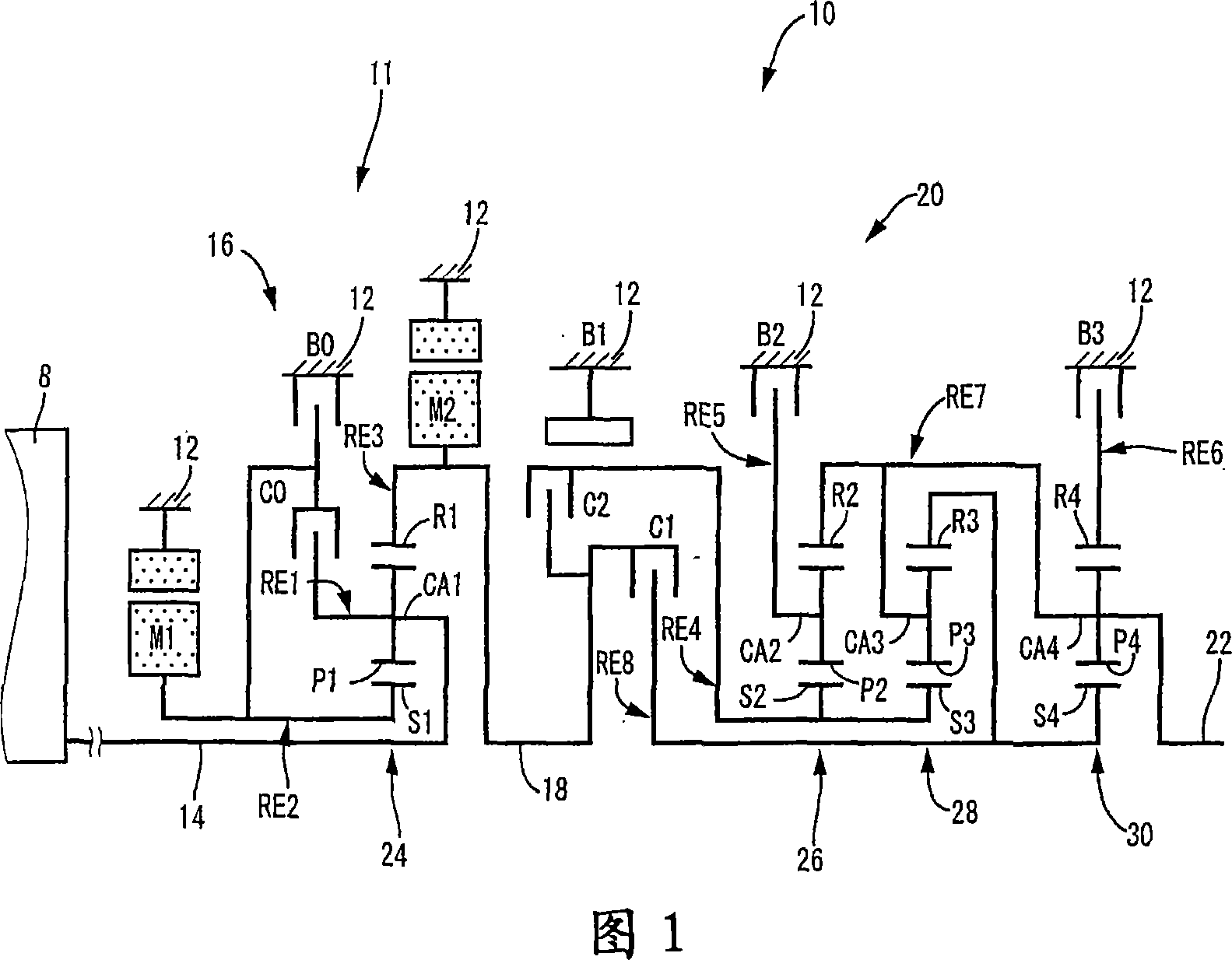
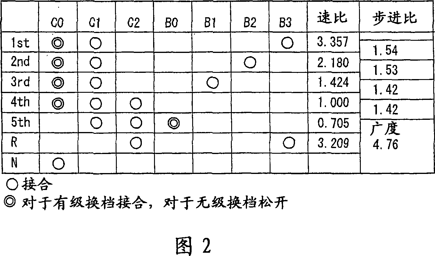
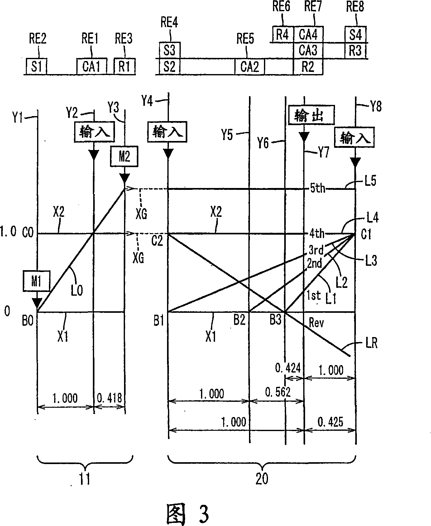
[0044] Referring to the schematic diagram of FIG. 1, there is shown a transmission mechanism 10 forming part of a drive system for a hybrid vehicle, the drive system being controlled by a control device according to an embodiment of the present invention. In FIG. 1 , a transmission mechanism 10 includes: an input rotary member in the form of an input shaft 14; a differential portion 11 connected to the input shaft 14 directly or indirectly via a pulsation absorbing damper (vibration damping device) not shown. A continuously variable transmission part in the form of; a stepped or multi-stage automatic transmission in the form of an automatic transmission part 20, which is arranged between the differential part 11 and the drive wheels 38 of the vehicle (shown in FIG. A transmission member 18 (power transmission shaft) is connected in series to the tran...
no. 2 example
[0152] 14 is a schematic diagram showing the arrangement of a transmission mechanism 70 according to another embodiment of the present invention, and FIG. 15 shows the gear positions of the transmission mechanism 70 and the engagement states of the hydraulically operated friction coupling devices for respectively establishing these gear positions. 16 is a collinear diagram for explaining the shift operation of the transmission mechanism 70.
[0153] The transmission mechanism 70 includes the differential portion 11 having the first electric machine M1, the power distribution mechanism 16, and the second electric machine M2, as in the previous embodiment. The transmission mechanism 70 also includes an automatic transmission portion 72 having three forward drive positions. The automatic transmission portion 72 is arranged between the differential portion 11 and the output shaft 22 , and is connected in series to the differential portion 11 and the output shaft 22 via the power t...
no. 3 example
[0162] 17 shows a toggle switch 44 (hereinafter referred to as "switch 44") used as a shift state selection device, which can be manually operated to select the differential state (non-lock state) or non-differential state of the power distribution mechanism 16. The speed state (locked state), that is, the continuously variable shift state or the step shift state of the transmission mechanism 10 is selected. This switch 44 allows the user to select a desired shift state while the vehicle is in motion. As shown in Figure 22, the interactive changeover switch 44 has a continuously variable shift travel button marked "with steps" for the vehicle running under the continuously variable shift state, and a continuously variable shift button for the vehicle under the step shift state. Stepped shift travel button marked "stepless" for travel. When the CVT travel button is pressed by the user, the switch 44 is placed in a CVT position for selecting a CVT state in which the transmissio...
PUM
 Abstract
Description
Claims
Application Information
 - R&D
- Intellectual Property
- Life Sciences
- Materials
- Tech Scout
- Unparalleled Data Quality
- Higher Quality Content
- 60% Fewer Hallucinations
Browse by: Latest US Patents, China's latest patents, Technical Efficacy Thesaurus, Application Domain, Technology Topic, Popular Technical Reports.
© 2025 PatSnap. All rights reserved.Legal|Privacy policy|Modern Slavery Act Transparency Statement|Sitemap|About US| Contact US: help@patsnap.com


