Paint booth

A painting room and painting technology, which is applied in the field of painting rooms, can solve problems such as constraints, low efficiency of painting operations, and increase of painting costs, so as to shorten the time of painting operations, improve the efficiency of painting operations, and reduce the The effect of the paint booth

Inactive Publication Date: 2007-10-31
上野 信
View PDF1 Cites 6 Cited by
  • Summary
  • Abstract
  • Description
  • Claims
  • Application Information

AI Technical Summary

Problems solved by technology

[0019] However, the painting room of Patent Document 1 has the following disadvantages: it is not necessarily cheap, and there are space constraints, the efficiency of painting work is not high, and even the painting cost has to be increased.

Method used


Image

  • Paint booth
  • Paint booth
  • Paint booth

Examples


Embodiment Construction

[0063] Next, a painting booth according to an embodiment of the present invention will be described with reference to the drawings.

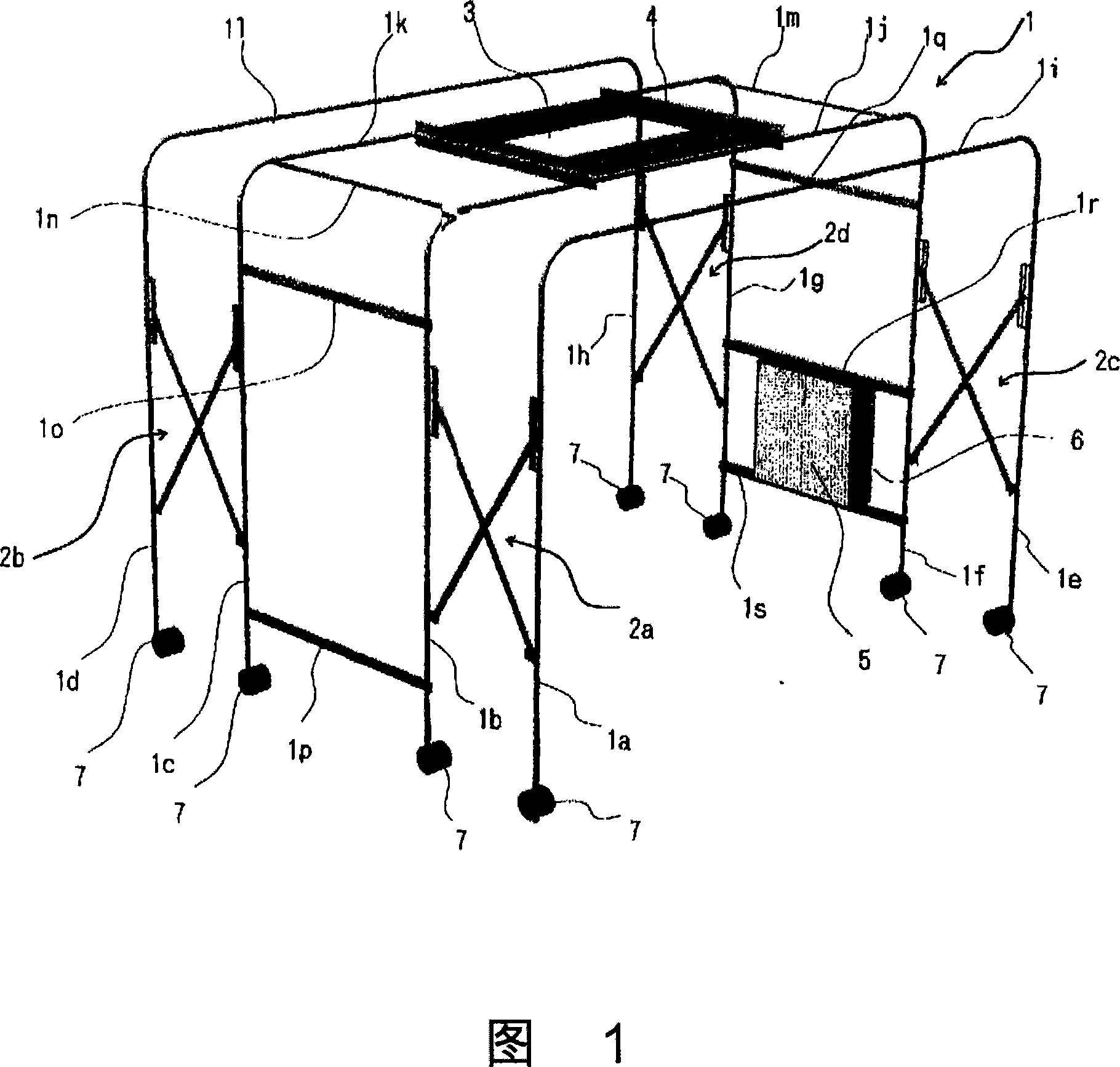
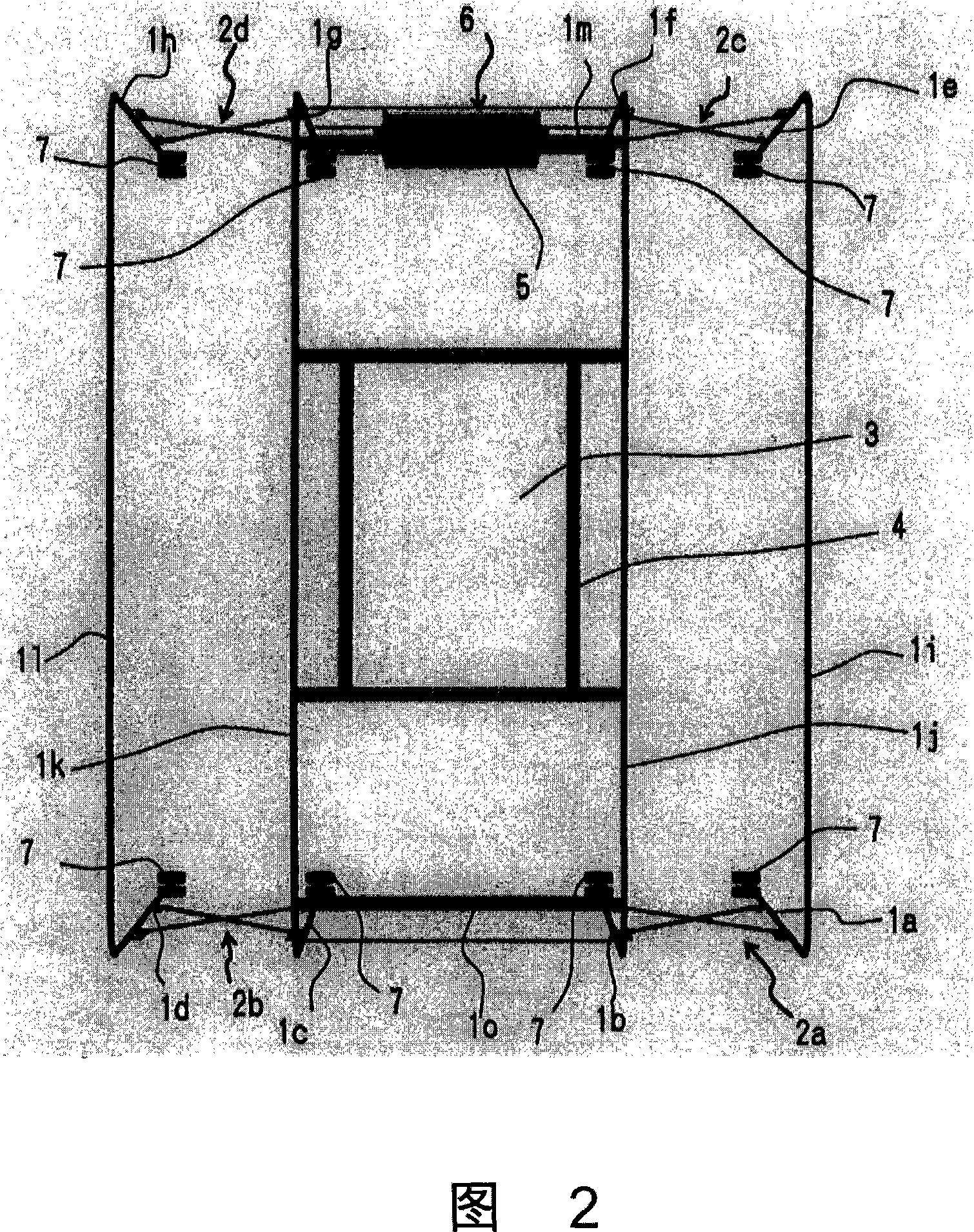
[0064] Fig. 1 is a schematic structural perspective view of the frame group member of the first embodiment of the painting booth according to the present invention seen obliquely from above, and Fig. 2 is a frame group of the painting booth shown in Fig. 1 seen from directly above A three-dimensional view of a model structure of a component, etc.

[0065] In Fig. 1 and Fig. 2, the skeleton group member 1 forms a roughly cuboid painting space as a whole, including: left and right four vertical frames 1a, 1b, 1c, 1d and 1e, 1f, 1g, 1h; top frames 1i, ij, 1k, 1l, 1m, 1n; horizontal frame 1o, 1p, 1q, 1r, 1s; zoom mechanism 2a, 2b and 2c, 2d.

[0066] In Fig. 1 and Fig. 2, the vertical frames 1a-1d, the top frames 1i-1l and the vertical frames 1e-1g are respectively integrally formed, but they can also be made into separate components and combined b...


PUM


Abstract

A painting spraying room covers the skeleton surface side except the undersurface of the skeleton group member (1) by cover member (8). The facade of the cover member (8) is stroked from the bottom up. An exhaust opening part (5) and an exhaust device mounting rack (6) with a filter, an exhaust fan and an extract duct around are set on the right side (8b). An air-supply opening part and a drier mounting rack (4) for installing the drier (10) are set on the upper surface (8e). The painting spraying room and the drier (10) can make a cross move together, so without engagement of workplaces, thereby increasing space efficiency. The invention can shorten coating operation time including drying time, thereby markedly enhancing coating working performance and increasing space efficiency in the workspace without choosing the workspace. It achieves the functions of reaching the environmental criteria and adequately suiting for the water paint.

Description

technical field [0001] The present invention relates to a painting booth, and more specifically, relates to a painting booth having a painting space capable of performing painting operations inside and capable of ventilating with the outside. Background technique [0002] Conventionally, a dry-type mask-type paint booth is generally known as such a paint booth. The baffle-type painting room is formed in a rectangular box shape with an open front, and a baffle as a first filter is erected inside the box-shaped room body, and a second filter is arranged behind the baffle. The exhaust chamber is formed behind the 2 filters. In addition, an exhaust fan is installed on the upper part of the exhaust chamber, and the air in the chamber body is exhausted through the exhaust chamber, the baffle, and the second filter through the exhaust action of the exhaust fan. [0003] When spraying paint from a spray coating gun in the chamber body, the spray mist sprayed from the spray gun int...

Claims


Application Information

Patent Timeline
Patent Type & Authority Applications(China)
IPC IPC(8): B05B15/12B05D3/00F24F7/013
CPCB05B14/435B05B15/40B05B16/20
Inventor 上野信
Owner 上野 信
Why Eureka
Try Eureka