Cracking furnace with radiation furnace tubes configured in U-shaped structure

A radiant furnace tube and cracking furnace technology, which is applied in the direction of hydrocarbon cracking, hydrocarbon production, organic chemistry, etc., can solve the problems affecting the circumferential temperature distribution of the furnace tube, etc., and achieve the effects of uniform force, large production capacity, and good mechanical properties

Active Publication Date: 2007-10-31
CHINA PETROLEUM & CHEM CORP +2
View PDF3 Cites 10 Cited by
  • Summary
  • Abstract
  • Description
  • Claims
  • Application Information

AI Technical Summary

Problems solved by technology

[0008] The arrangement of the furnace tubes has developed from the initial single row to double rows. For a single row, the same capacity requires a larger footprint. The advantage is that the circumferential temperature distribution of the furnace t...

Method used


Image

  • Cracking furnace with radiation furnace tubes configured in U-shaped structure
  • Cracking furnace with radiation furnace tubes configured in U-shaped structure
  • Cracking furnace with radiation furnace tubes configured in U-shaped structure

Examples


Embodiment Construction

[0073] Provide an embodiment below in conjunction with accompanying drawing 47. The following descriptions only represent specific embodiments of the present invention, and are only used to further illustrate the present invention, but not to limit the present invention.

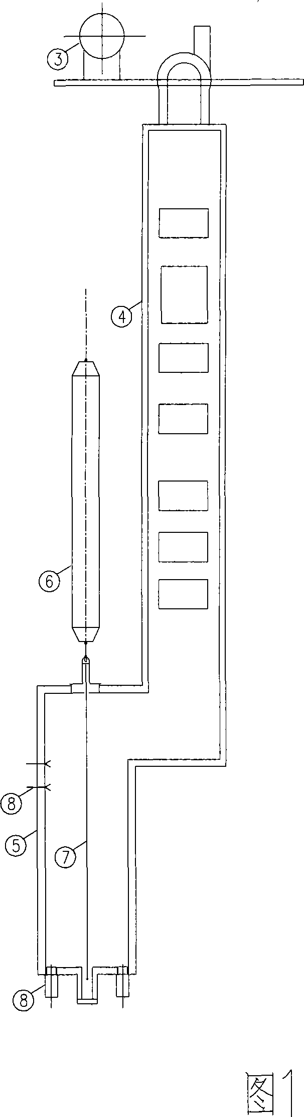
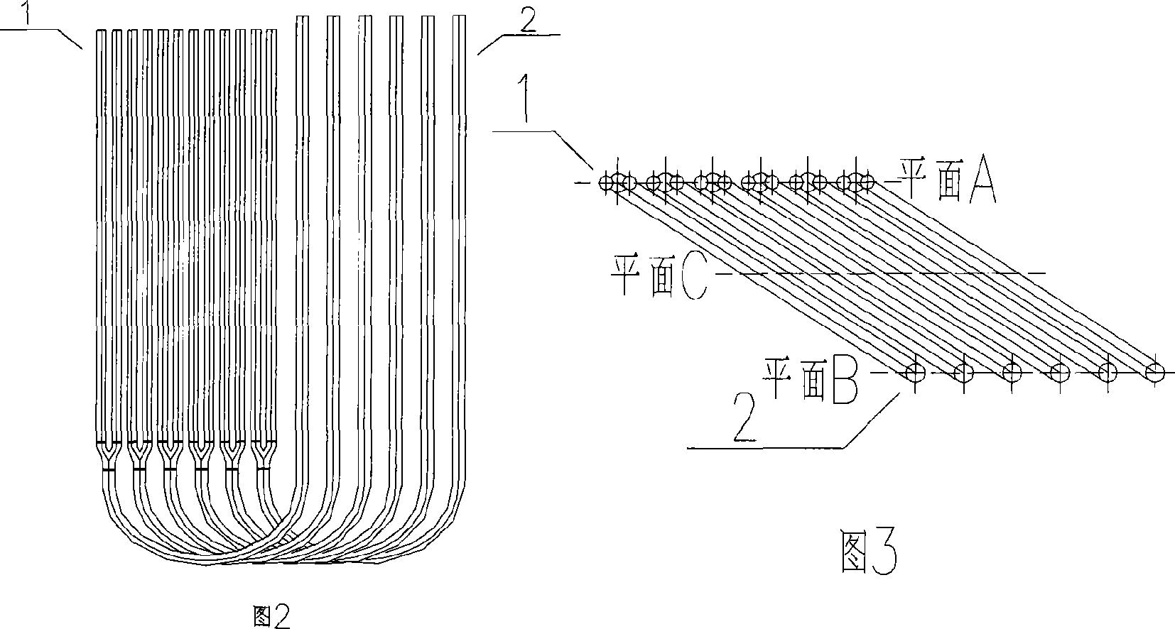
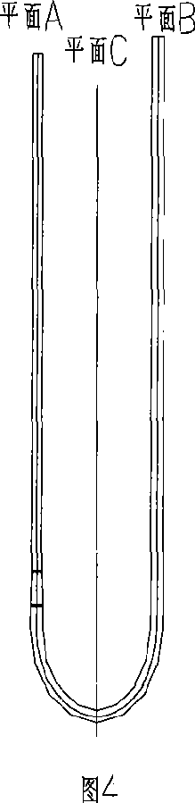
[0074] The cracking furnace of the present invention comprises a high-pressure gas bag 3, a convection section 4, a radiation section 5, a plurality of groups of radiation furnace tubes 7, a burner 8, and a quench boiler 6 vertically arranged in the radiation section; Length 14000mm. Each two-pass vertical radiation furnace tube arranged in a 2-1 pattern is composed of the first-pass tube 1 and the second-pass tube 2, and the first-pass tube and the second-pass tube are connected by a semicircular elbow connector; The pyrolysis material is introduced from the first pass pipe and drawn out from the second pass pipe. The upper part of the first pass pipe is two inlet pipes, which are combined by a three-way ...


PUM


Abstract

The invention discloses an ethylene cracking furnace, which is characterized by the following: setting radiant section furnace pipe of this cracking furnace as two range vertical furnace pipe; connecting with back bending pipe connecting piece between the first range pipe and the second range pipe; setting normal view projection and lateral view projection as 'U' shape; arranging the first range pipe and the second range pipe in the two plan A and B of each radiant furnace pipe. This invention possesses simple structure, which can decrease operating expense and extending durability of the furnace tube.

Description

technical field [0001] The invention relates to an ethylene cracking furnace. Background technique [0002] In the ethylene plant, the cracking furnace is the core equipment. The design of the radiant coil is the key to determine the cracking selectivity, improve the yield of cracked olefins and improve the adaptability to different cracking raw materials. Improving the structure and arrangement of radiant coils has become the core part of the development of tubular cracking furnace technology. For more than 20 years, there have been radiant coils with different structures such as single-row branch reducer, mixed-row branch reducer, non-branch reducer, and single-pass equal-diameter pipe. [0003] In order to greatly reduce raw material consumption, maintain an appropriate operating cycle and have better raw material adaptability, most companies currently use two-pass (18-28m) branch variable diameter or two-pass variable diameter high-selectivity furnace tubes, which will...

Claims


Application Information

Patent Timeline
IPC IPC(8): C07C11/04C07C4/02
Inventor 何细藕李昌力张兆斌周丛孙向军杜志国张磊张永刚邵晨陈永亮李光
Owner CHINA PETROLEUM & CHEM CORP
Why Eureka
Try Eureka