
Home long-distance management device

A technology of remote management device and main controller, which is applied in the direction of data exchange, electrical components, telephone communication, etc. through path configuration, which can solve the problems of complex system structure, limited operating distance, high cost, etc., and achieve cost reduction and reduction Development cost, effect of increasing cost

Inactive Publication Date: 2007-11-07
HARBIN ENG UNIV
View PDF2 Cites 4 Cited by
  • Summary
  • Abstract
  • Description
  • Claims
  • Application Information

AI Technical Summary

Problems solved by technology

All these designs are for residential quarters, and special bus systems are required, which are only suitable for new residential quarters. If they are to be used in old residential quarters, major renovations must be carried out, and the high cost is not suitable for the promotion of a single family.
In addition, this type of smart residence has a short range of action, and its application is limited to the area of ​​the community or building.
[0003] The invention patent "Computer Security and Home Appliance Intelligent Control System" (Patent No. 00106464.9) takes a single family as the service object, and proposes a computer security and home appliance intelligent control system. Realize remote control
Although it achieves the purpose of remote alarm, a dedicated GSM module must be used, and the cost is high and it is not suitable for the promotion of home applications.
Moreover, this system only has an alarm function, and cannot realize remote operation of home appliances, nor is it a home management system.

Method used


Image

  • Home long-distance management device
  • Home long-distance management device
  • Home long-distance management device

Examples


specific Embodiment approach 1

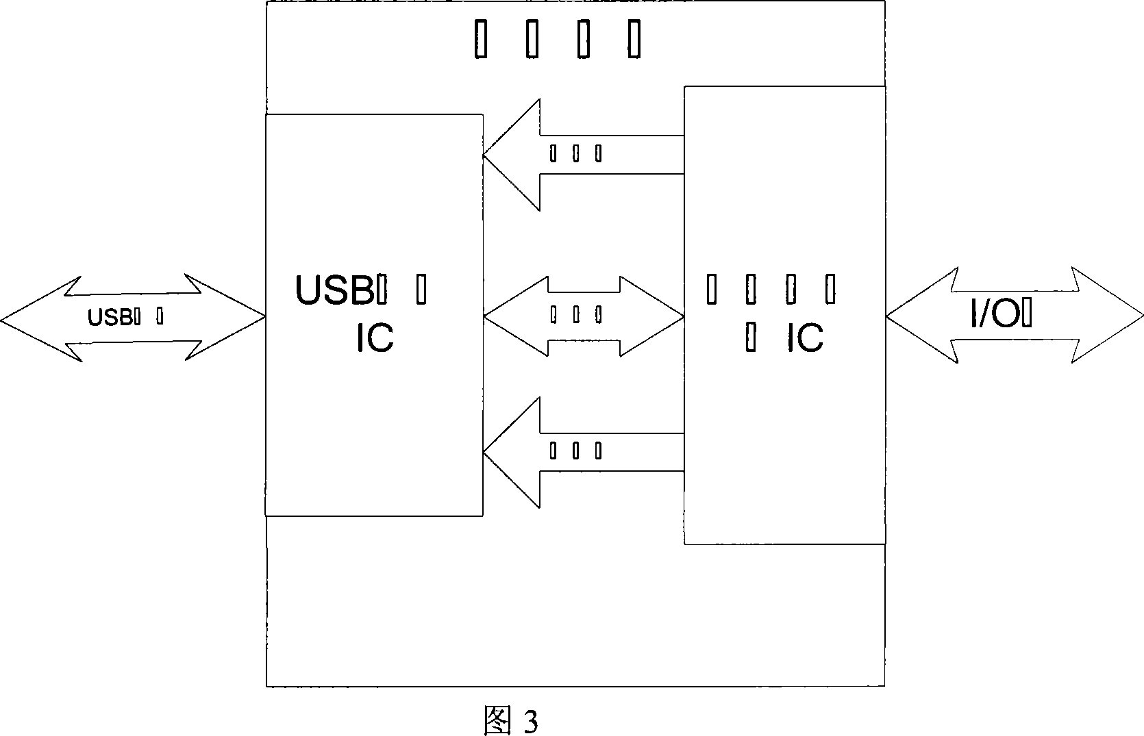
[0041] Main controller circuit composition:

[0042] The programmable logic IC is selected as AT89C52 of ATMEL Company, which has a wide range of applications and contains multiple I / O ports. It is a high-performance single-chip microcomputer suitable for this system. The application circuit of AT89C52 is shown in Figure 6.

[0043]This circuit contains the minimum application system of AT89C52, including: reset circuit (peripheral circuit connected to pin 9), oscillation circuit (peripheral circuit connected to pin 19 and 18), power supply (pin 40 connected to VCC (5V), pin 20 ground (not marked in the figure)). In addition, the P0 port (pins 32 to 39) of AT89C52 is connected to the data port of CH375. Connect pin 21 of AT89C52 to pin 8 of CH375 (circuit diagram 7) as an address line. Pins 17, 16, 22, and 12 of AT89C52 are respectively connected to pins 4, 3, 27, and 1 of CH375 as control lines. Port P1 (pins 1 to 8) and port P2 (pins 21 to 28) serve as I / O ports. By pro...

specific Embodiment approach 2

[0057] On the basis of Scheme 1, modify the security inspection subsystem to obtain Scheme 2.

[0058] In scheme two, the security inspection subsystem is still composed of a password proofreader, an electronic key and a door open detector. But the specific implementation is different. The password proofreader adopts programmable IC-AT89C52, and there are corresponding programs in it. The electronic key adopts a common USB flash drive, and the door open detector adopts a proximity Hall switch. AT89C52 adopts the same circuit connection method as AT89C52 in the main controller in the specific implementation plan 1 to establish a USB interface, so it will not be repeated here. In addition, pin 1 of AT89C52 is connected to the output of the Hall sensor. The hall sensor sets pin 1 high when the door is closed and the hall sensor sets pin 1 low when the door is open. Get the state of the gate by judging the level of pin 1. Pins 10 and 11 of AT89C52 are respectively connected t...


PUM


Abstract

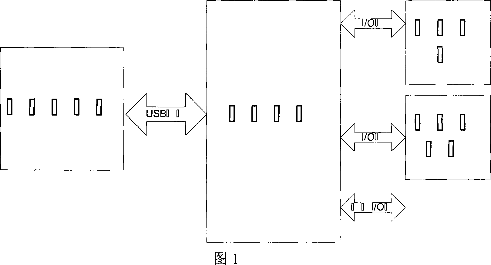
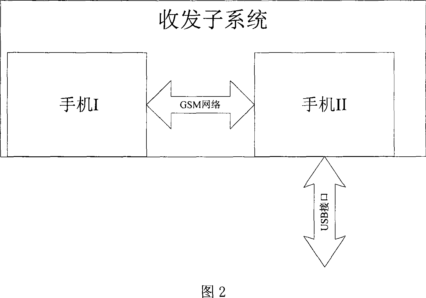
A remote management device of home safety is prepared as connecting master controller with transmitting / receiving subunit to each other through USB interface and connecting master controller with safety inspection subunit and electric appliance interface to each other through I / O interface.

Description

(1) Technical field [0001] The present invention designs a management device, specifically a device for remote operation and management of daily life households. (2) Background technology [0002] With the advancement and development of science and technology, people have higher expectations for the quality of daily life. Related technologies related to home management are developing rapidly. First, the concept of smart housing was raised in the United States, and then developed countries such as Europe, Japan, and Singapore successively proposed the concept of "smart home (Smart Home)", and the intelligentization of housing has also developed rapidly. Up to now, an intelligent building system based on security monitoring has been formed. In Japan, the Ministry of Posts and Telecommunications and the Ministry of International Trade and Industry organized the Japanese Machinery Industry Association and the Radio Technology Association to jointly form the HBS Standards Commi...

Claims


Application Information

Patent Timeline
IPC IPC(8): H04M11/00H04L12/28
Inventor 邓辉峰杨东升季宝锋陈东良刘德峰贾守波宋辉
Owner HARBIN ENG UNIV
Learn More