Linear amplifier and its high power pulse power source

A technology of linear amplifiers and operational amplifiers, applied in amplifiers with multiple amplifying elements, etc., can solve problems such as difficulty in ensuring system requirements, low withstand voltage of linear devices, and difficulty in ensuring system stability.

Active Publication Date: 2007-11-14
XINFENGGUANG ELECTRONICS TECH CO LTD
View PDF0 Cites 11 Cited by
  • Summary
  • Abstract
  • Description
  • Claims
  • Application Information

AI Technical Summary

Problems solved by technology

[0002] When power devices are used as switching devices in parallel to realize high current, small tracking error, low duty cycle, and controllable power supply of output current pulse, there is response delay caused by modulation process, and the output needs to be low-pass filtered, so in the control It is not easy to ensure the stability of the system in the closed-loop control
[0003] If linear device field effect transistors or transistors are used to implement, the withstand voltage of linear devices is relatively low, and it is difficult to guarantee the system requirements.

Method used


Image

  • Linear amplifier and its high power pulse power source

Examples


Embodiment Construction

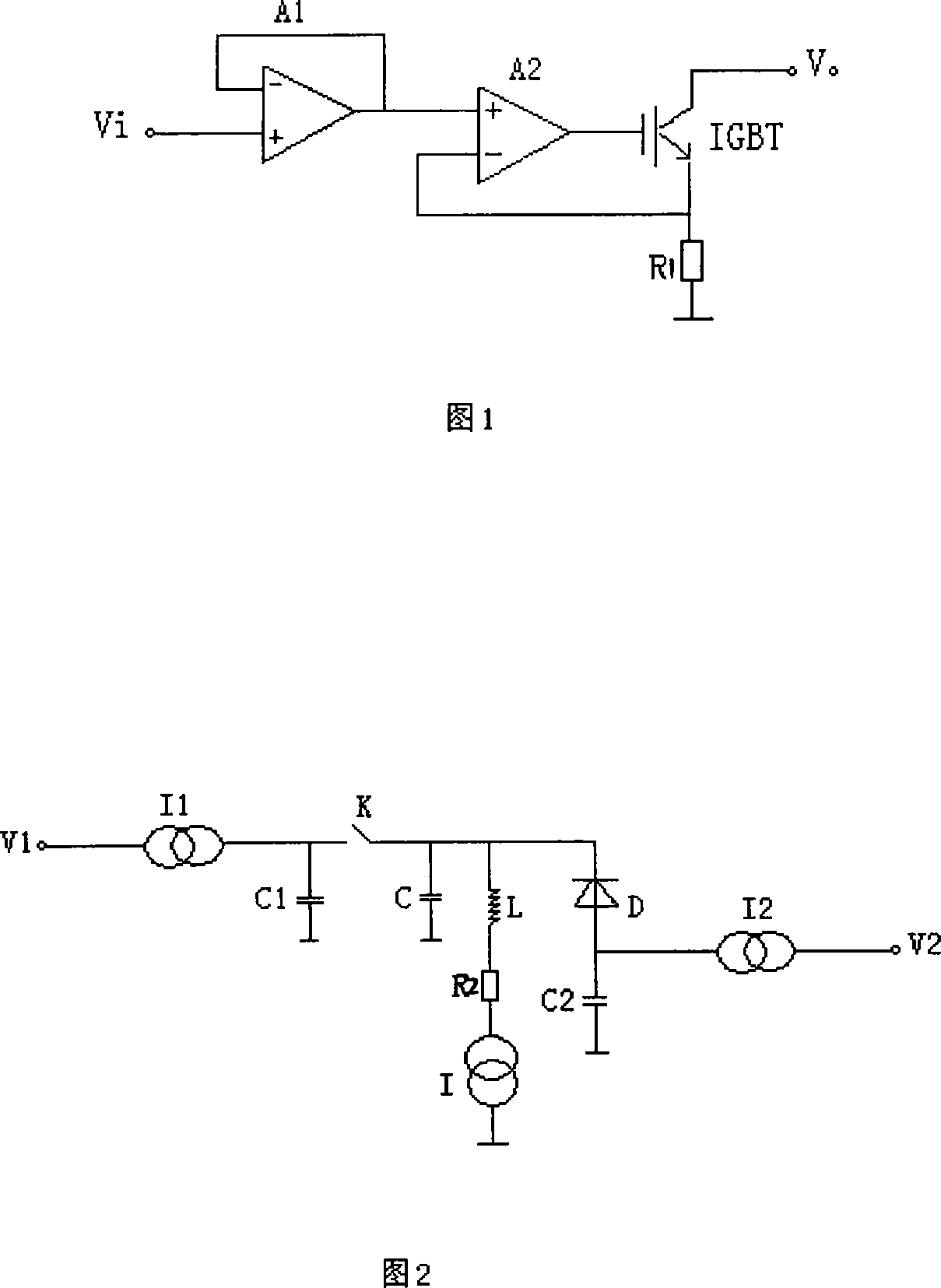
[0017] The present invention will be specifically described below in conjunction with the accompanying drawings and specific embodiments.

[0018] As shown in accompanying drawing 1, it is a schematic circuit diagram of a method for realizing a high-power pulse power supply by using the power device IGBT as a linear device. It is composed of two operational amplifiers A1 and A2 connected in series and an emitter follower connected in series with an IGBT. The collector output is connected to the current negative feedback amplifier, one end of the non-inductive resistor R1 is respectively connected to the reverse end of the emitter follower A2 and the emitter of the IGBT, and the other end of the non-inductive resistor R1 is grounded to form a linear amplifier.

[0019] Accompanying drawing 2 is the schematic diagram of the current linear amplifier power supply system (high-power pulse power supply), which consists of two controllable voltages V1 and V2, two current sources I1 an...


PUM


Abstract

The invention is related to linear amplifier (LA), and high power pulse electrical source (HPPES). LA uses power unit IGBT as linear unit. HPPES uses LA. LA is composed of two operational amplifiers, one power unit IGBT, and a non-inductive resistance. HPPES consists of a main current source, two current sources I1 and I2, two controllable voltages, three capacitors, switch K, diode D, inductance L, and non-inductive current limiting resistance. Whole circuit forms controllable linear current source with good tracking performance, and characteristic of constant current source. Using variable supply power, HPPES lowers wastage of power unit so as to raise efficiency of system.

Description

(1) Technical field [0001] The invention relates to a linear amplifier using a power device IGBT as a linear device, and a high-power pulse power supply using the linear amplifier, belonging to the technical field of power electronics and power supply. (2) Background technology [0002] When power devices are used as switching devices in parallel to realize high current, small tracking error, low duty cycle, and controllable power supply of output current pulse, there is response delay caused by modulation process, and the output needs to be low-pass filtered, so in the control It is difficult to guarantee the stability of the system in the closed-loop control. [0003] If a linear device field effect tube or transistor is used to implement, the withstand voltage of the linear device is relatively low, and it is difficult to guarantee the system requirements. (3) Contents of the invention [0004] In order to solve the deficiencies of the above technologies, the present i...

Claims


Application Information

Patent Timeline
Patent Type & Authority Applications(China)
IPC IPC(8): H03F3/42
Inventor 何洪臣李瑞来方汉学胡顺全尹彭飞
Owner XINFENGGUANG ELECTRONICS TECH CO LTD
Why Eureka
Try Eureka