Floor panel and method for manufacturing a floor panel

A floor, area technology, used in the field of manufacturing floors, laminate floors, to solve problems such as unsatisfactory

Active Publication Date: 2007-11-14
FLOORING IND LTD
View PDF9 Cites 61 Cited by
  • Summary
  • Abstract
  • Description
  • Claims
  • Application Information

AI Technical Summary

Problems solved by technology

[0004] Common techniques lead to unsatisfactory results when imitating c...

Method used


Image

  • Floor panel and method for manufacturing a floor panel
  • Floor panel and method for manufacturing a floor panel
  • Floor panel and method for manufacturing a floor panel

Examples


Embodiment Construction

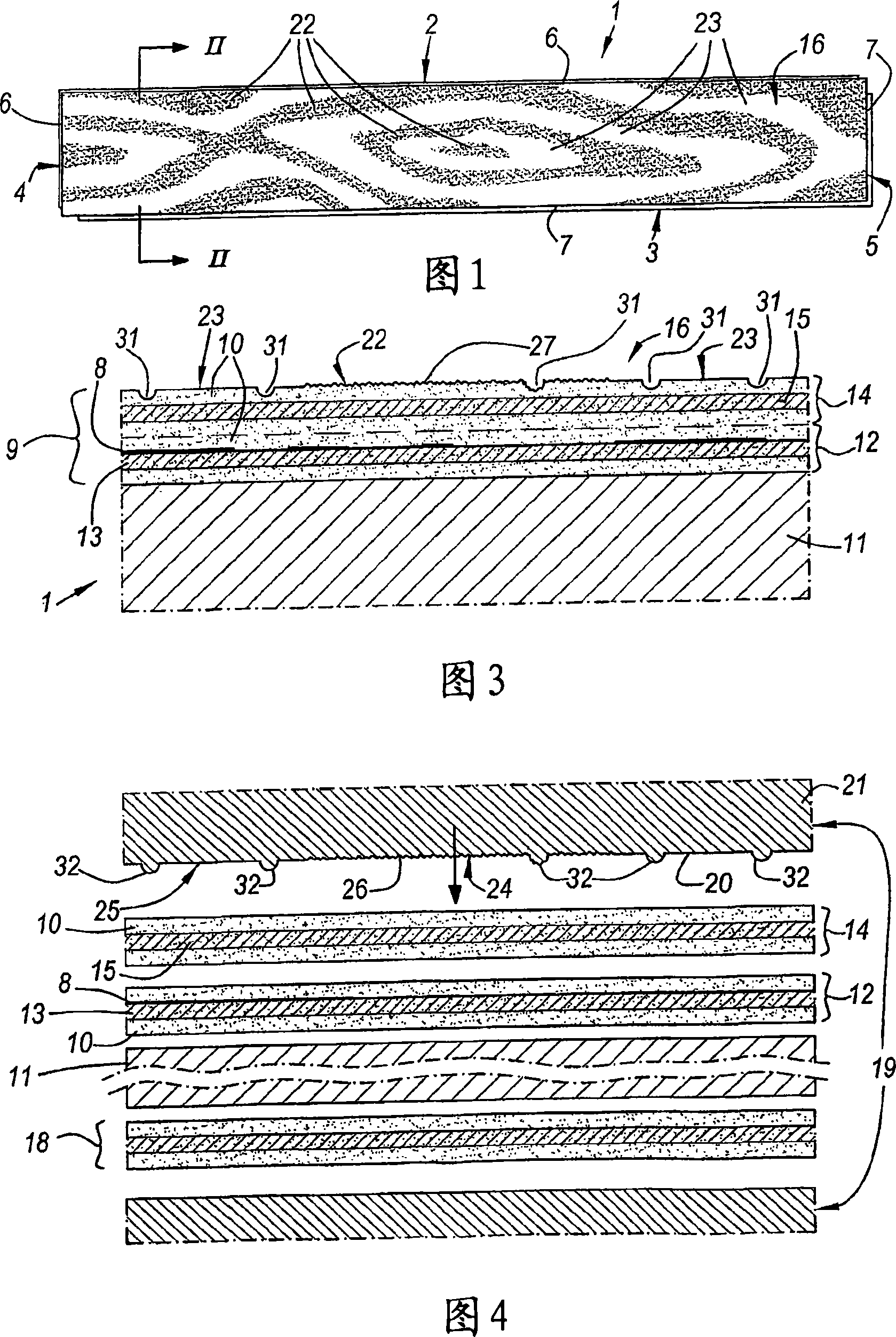
[0095] As shown in FIG. 1 , the invention relates inter alia according to its first aspect to a floor 1 of the type intended for forming a floating floor covering.

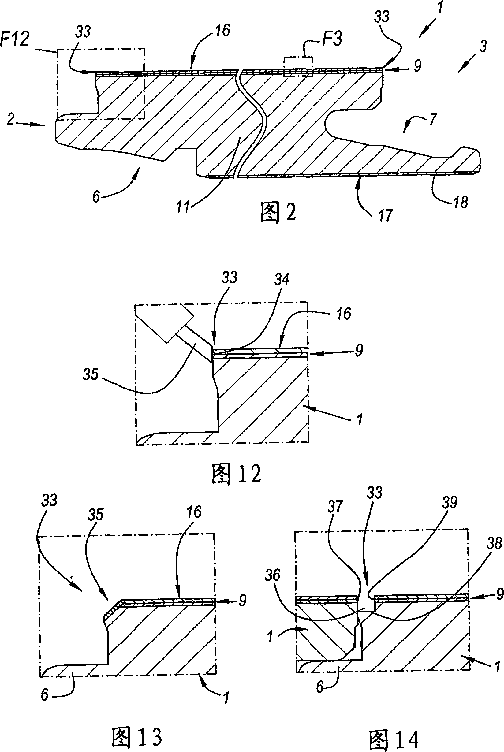
[0096] As shown in Figures 1 and 2, the floor panel 1 is preferably provided with coupling portions 6-7 at least at two opposite edges 2-3, and preferably at two pairs of opposite edges 2-3 and 4-5, By means of the coupling portion 6-7 a plurality of such floor panels 1 can be coupled to each other. As shown in the figure, these coupling parts 6-7 are preferably of the type that, in the coupled state of the floor panel 1, a locking in vertical and height direction is achieved. According to the variants, other types of coupling parts are not excluded, for example coupling parts in the form of normal tongues and grooves, or coupling parts for realizing so-called "drop-in" couplings. The joint part does not need to be manufactured in one piece with the floor body. It is possible to combine several types of joint pa...


PUM


Abstract

4-Amino substituted-2-substituted-1,2,3,4-tetrahydroquinoline compounds, pharmaceutical compositions containing such compounds and the use of such compounds to elevate certain plasma lipid levels, including high density lipoprotein-cholesterol and to lower certain other plasma lipid levels, such as LDL-cholesterol and triglycerides and accordingly to treat diseases which are exacerbated by low levels of HDL cholesterol and/or high levels of LDL-cholesterol and triglycerides, such as atherosclerosis and cardiovascular diseases in some mammals, including humans.

Description

technical field [0001] The present invention relates to a floor, more particularly a laminate floor, and a method for the manufacture of the floor. [0002] In particular, the invention relates to floors of the type intended to form a floating floor covering comprising a decorative surface, preferably a printed decorative surface, and a top layer based on synthetic material, and The decorative sides of the floor imitate a wood grain pattern. Background technique [0003] It is known that wooden floor parts or parquet floors are often imitated with laminate floors. It is known that such imitation is mostly achieved by providing the floor with a printed decorative surface representing a photographic image of the wood. [0004] When imitating certain species of wood, above all dark and / or exotic wood species such as Wenge, common techniques lead to unsatisfactory results. Contents of the invention [0005] The general purpose of the present invention is to provide a new ty...

Claims


Application Information

Patent Timeline
IPC IPC(8): B44C5/04E04F15/10B44F9/02
CPCB44C5/04B44F9/02
Inventor O·诺莱C·内耶尔特
Owner FLOORING IND LTD
Why Eureka
Try Eureka