Method for controlling emergent brake fault

A technology for preventing mistakes and stepping on the accelerator by mistake. It is applied in the directions of engine control, power unit control mechanism layout, electrical control, etc. It can solve the problems of no automatic driving, relying on manual driving, and vehicle collision, etc., and increase the economic added value. , Improve the level of automation technology, the effect of fast response

Inactive Publication Date: 2007-11-21
SHANGHAI JIAO TONG UNIV
View PDF0 Cites 12 Cited by
  • Summary
  • Abstract
  • Description
  • Claims
  • Application Information

AI Technical Summary

Problems solved by technology

Among them, during the driving process of the car, there is a sudden special situation ahead, such as: a person suddenly crosses the road, the vehicle in front brakes suddenly, etc., because the driver is nervous or unable to react in time, the emergency brake should be performed, but the accelerator is stepped on by mistake, so Major accidents that cause vehicle crashes into people or vehicle rear-end collisions, etc.
[0003] Although the technology developed around the automobile industry in the world has been quite developed, and people are constantly pursuing technical devices and methods that attempt to realize the fully automatic driving of automobiles, so far, there is still no technologically advanced and mature technology. For self-driving cars, existing vehicles still need to rely on manual driving, especially when the car encounters an emergency and needs to brake in an emergency, it completely depends on the driver's on-the-spot performance to ensure driving safety. Therefore, the car has emergency brakes to prevent accidental stepping Automatic control technology is absolutely necessary, even in the era when fully automatic driverless cars appear in the future, it can be foreseen that the core technology of the present invention has become one of the constituent technologies of new cars
[0004] After searching the literature of the prior art, it was

Method used


Image

  • Method for controlling emergent brake fault
  • Method for controlling emergent brake fault
  • Method for controlling emergent brake fault

Examples


Embodiment Construction

[0022] The following is a detailed description of the embodiments of the present invention: this embodiment is implemented on the premise of the technical solution of the present invention, and gives a detailed implementation mode and specific operation process, but the protection scope of the present invention is not limited to the following implementations example.

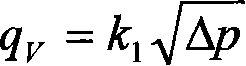
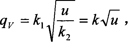
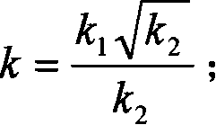
[0023] This embodiment is implemented based on an emergency brake anti-misstepping device. The device includes: a signal processor, a controller, a measurable and controllable solenoid valve, a first electronic switch, a second electronic switch, an electric push rod, a brake, and can be measured and controlled. The solenoid valve is installed on the upstream side of the accelerator pedal of the fuel supply pipeline of the automobile, and the electric push rod is installed on the extension end of the heavy arm of the pedal brake plate. The signal processor receives the differential pressure of the oil circuit fluid ...


PUM


Abstract

The invention is concerned with an auto-control method for preventing from urgent braking and pressing accelerator pedal mistakenly belonging to auto-control technology field. The testable electromagnetism valve sets on the upriver side of throttle for step and sends the pressure different of fuel to the upper and lower steam of the valve to the pressure intake port of pressure different sensor. The pressure different of flow changes into electric signal of flow pressure different by the sense organ in the sensor and sends to the intake end of signal processor. Set criterion of urgent braking and pressing accelerator pedal mistakenly as the determinant threshold value according to vehicle's type in the signal processor, and the signal processor will judge and estimate according to the instantaneous flow to fuel. When it judges the mistake of braking, it will send braking order to controller to close the testable electromagnetism valve and cut off the fuel through electronic switch, at the same time, the electric pushing pole drives the car to stop to avoid traffic accident.

Description

Technical field [0001] The invention relates to a method in the technical field of automatic control, and in particular to an automatic control method for preventing the driver from stepping on the accelerator by mistake when an automobile brakes suddenly. Background technique [0002] With the development of world economy and science and technology, while automobiles are becoming more and more popular, traffic accidents happen frequently. There are not a few serious accidents caused by car drivers' misoperations, which need to rely on the improvement of the corresponding technical level to avoid them. Among them, when the car is driving, special circumstances suddenly occur in the front, such as: people suddenly cross the road, the vehicle in front suddenly brakes, etc., because the driver's heart is nervous or unable to respond, the emergency brake should be used, but the accelerator is stepped on by mistake. Major accidents that cause car crashes or rear-end collisions and oth...

Claims


Application Information

Patent Timeline
IPC IPC(8): B60K26/02F02D41/02B60T7/06B60W10/06B60W10/18B60W30/08
Inventor 张秀彬张晓芳朱晓乾周丛嘉李君峰
Owner SHANGHAI JIAO TONG UNIV
Why Eureka
Try Eureka