Sagnac optical-fiber deformation sensor of low-coherent twisted torqued

A fiber deformation and sensing device technology, applied in the direction of using optical devices, measuring devices, instruments, etc., can solve the problems of inability to realize distributed measurement, high cost, etc., to improve multi-channel coherent multiplexing capability, low cost, reduce The effect of light loss

A fiber deformation and sensing device technology, applied in the direction of using optical devices, measuring devices, instruments, etc., can solve the problems of inability to realize distributed measurement, high cost, etc., to improve multi-channel coherent multiplexing capability, low cost, reduce The effect of light loss

CN101074867AInactive Publication Date: 2007-11-21HARBIN ENG UNIV

Image

  • Sagnac optical-fiber deformation sensor of low-coherent twisted torqued
  • Sagnac optical-fiber deformation sensor of low-coherent twisted torqued

Examples


Embodiment Construction

[0018] The present invention is described in more detail below in conjunction with accompanying drawing example:

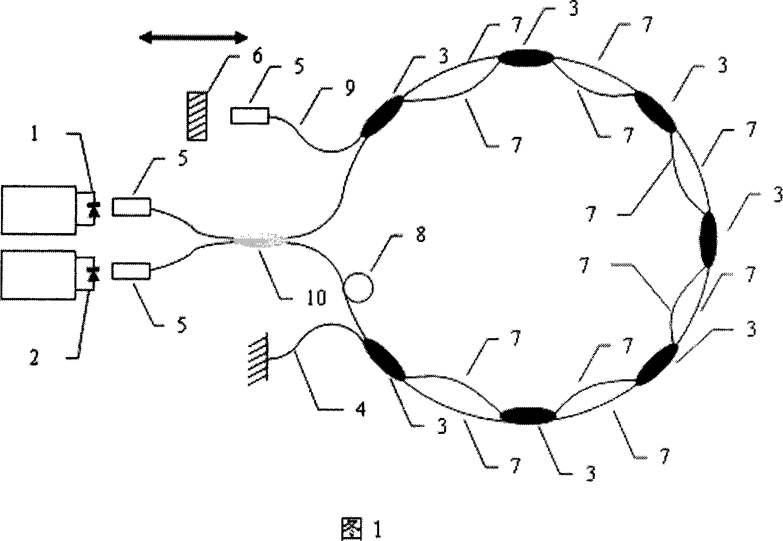
[0019] Referring to Fig. 1, the first embodiment of the present invention includes a wide-spectrum low-coherence LED light source 1, a photodetector 2, a 2×2 (3db) coupler 10, a 2×2 (3db) coupler 3, a high-reflection end-face single Mode optical fiber 4, self-focusing lens 5, scanning mirror 6, single-mode optical fiber sensing arm 7, polarization controller 8 and single-mode output optical fiber 9.

[0020] The light source 1 and the photodetector 2 are connected in parallel on one side of the coupler 10 through the self-focusing lens 5, and the other side of the coupler 10 is connected to a closed loop, in which a plurality of 2×2 couplers 3 Each section of single-mode optical fiber sensing arm 7 is connected in series to form a closed loop, and the high-reflection end-face single-mode optical fiber 4 and single-mode output optical fiber 9 are respectively place...


PUM


Abstract

A Sagnac-like optical fiber sending device of low coherent twisted type is prepared as connecting optical source and photoelectric detector at a side of a coupler and connecting another side of said coupler to a closed loop formed by series-connecting various single-mode optical sending arms with 2x2 couplers. The closed loop is featured as out-setting single-mode optical fiber of high reflection surface and single-mode out-set optical fiber, using self-focusing lens and scan-reflector to form demodulation end of optical fiber and returning partial light back to light detector through said single-mode optical fiber.

Description

(1) Technical field [0001] The invention relates to an optical fiber deformation sensing device, which belongs to the technical field of optical fiber sensing, in particular to a sensing device for distributed measurement of deformation based on an optical low-coherence interference measurement technology. (2) Background technology [0002] Compared with traditional sensors, optical fiber sensors have the advantages of strong anti-electromagnetic interference ability, high temperature resistance, high pressure resistance, strong chemical corrosion resistance, light weight, high sensitivity, low loss and easy realization of distributed sensing. Since the mid-1970s, Research has grown into an emerging industry with an annual turnover of more than US$1 billion and is expected to have a market of more than US$5 billion in 2010. According to the statistics of the 15th annual International Optical Fiber Sensing Conference (OFS) sponsored by the Society of Optical Engineers (OSA), ...

Claims


Application Information

Patent Timeline
21 Nov 2007
Publication
CN101074867A
IPC
G01B11/16
Inventors
è‹‘ç«‹æłą; æšć†›