A New Condenser Microphone Diaphragm and Its Condenser Microphone

A capacitor microphone and capacitor technology, applied in the direction of electrostatic transducer microphones, electromechanical sensors, sensors, etc., can solve problems such as limiting transduction efficiency, diaphragm fatigue, distortion, etc., to avoid partition vibration, reduce initial stress, and improve performance Effect

Inactive Publication Date: 2011-12-07
郑润远
View PDF0 Cites 0 Cited by
  • Summary
  • Abstract
  • Description
  • Claims
  • Application Information

AI Technical Summary

Problems solved by technology

Since the diaphragm works under permanent tension, there are several problems. First, the initial stress of the diaphragm is very high, which limits the response level of the dynamic lower limit of the microphone and causes distortion, especially when used as a high-quality When picking up sound, the weak harmonic information other than the fundamental frequency in the sound wave cannot respond; secondly, due to the clamping effect of the diaphragm ring on the diaphragm, the end of the diaphragm cannot produce substantial vibration when the diaphragm is excited by sound pressure during the transduction process. Due to the permanent displacement, only a small area in the central part of the diaphragm contributes to the energy conversion, thus limiting the efficiency of the energy conversion and the improvement of the sensitivity of the microphone; third, the permanent tension of the diaphragm will cause the fatigue of the diaphragm and affect the Microphone lifetime and reliability

Method used


Image

  • A New Condenser Microphone Diaphragm and Its Condenser Microphone
  • A New Condenser Microphone Diaphragm and Its Condenser Microphone
  • A New Condenser Microphone Diaphragm and Its Condenser Microphone

Examples


Embodiment Construction

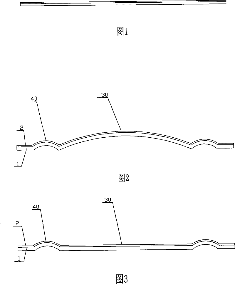
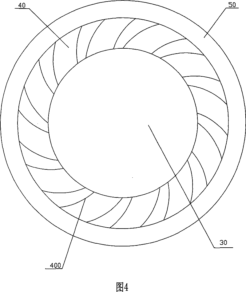
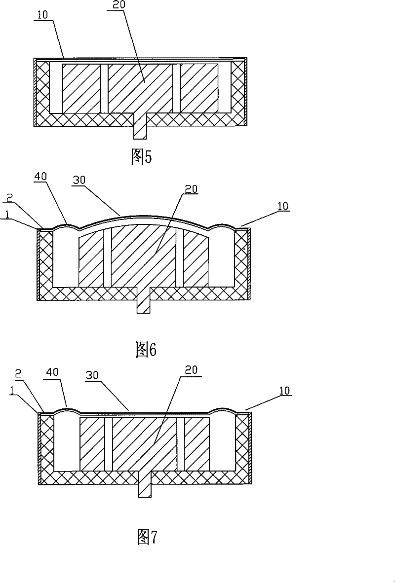
[0019] refer to figure 2 , image 3 , Figure 4 , a novel capacitor microphone diaphragm of the present invention, the diaphragm includes a diaphragm 1, the upper surface of the diaphragm 1 is coated with a metal film layer 2, the central part of the diaphragm is an effective transducing capacitor part 30, and its edge There are one or more arc-shaped protruding rings 40 for suspending / supporting the effective transducing capacitor part 30, which can effectively reduce the initial stress of the diaphragm and make the whole vibration system have sufficient elasticity. The production of the diaphragm is to firstly press the plastic film and then carry out electroplating; or to carry out electroplating on the plastic film and then carry out press molding.

[0020] As an embodiment of the present invention, refer to image 3 As shown, the effective transducing capacitor portion 30 of the diaphragm can be planar.

[0021] And further, of course, as a preferred embodiment of th...


PUM


Abstract

The invention discloses a novel capacitor microphone diaphragm, the diaphragm includes a diaphragm, the upper surface of the diaphragm is plated with a metal film layer, the central part of the diaphragm is an effective transducing capacitor part, and the edge of the diaphragm is used for suspension / One or more arc-shaped protruding rings supporting the effective transducing capacitor part; since the edge part of the diaphragm is an arc-shaped protruding ring, the protruding ring suspends / supports the central part of the diaphragm, effectively achieving slow tension The effect can significantly reduce the initial stress of the diaphragm, and can make the entire vibration system have sufficient flexibility when the energy is transduced. A metal layer is plated on the upper part of the diaphragm to form a transducing capacitor with the back electrode below the diaphragm. In addition, the metal coating can further enhance the rigidity of the sound-receiving surface of the diaphragm and prevent the diaphragm from generating partition vibration within the effective frequency range. , so that the performance of the condenser microphone is significantly improved.

Description

technical field [0001] The invention relates to a diaphragm of a condenser microphone and a microphone thereof. Background technique [0002] Existing condenser microphones include three forms, namely the externally polarized voltage condenser microphone, the diaphragm electret condenser microphone and the back pole electret condenser microphone. Regardless of the type of condenser microphone, they have at least a transducing capacitor consisting of a diaphragm and a back plate. [0003] At present, the diaphragm of the condenser microphone is usually a diaphragm with a flat structure, see figure 1 , Figure 5 Its structure is to use a diaphragm ring to stretch a metal foil or a plastic film coated with a metal conductive layer on one side, and then use adhesive, clamping or other methods to tightly fix the diaphragm on the diaphragm ring. Since the diaphragm works under permanent tension, there are several problems. First, the initial stress of the diaphragm is very high...

Claims


Application Information

Patent Timeline
Patent Type & Authority Patents(China)
IPC IPC(8): H04R19/01H04R19/04H04R7/00
Inventor 郑润远
Owner 郑润远
Why Eureka
Try Eureka