Capacitive microphone diaphragm, microphone and production method thereof

A capacitor and microphone technology, applied in non-planar diaphragm/paper cone, electrical components, diaphragm structure, etc., can solve the problems of reducing timbre, diaphragm fatigue, and high initial stress of diaphragm, and improve service life and reliability. , the effect of reducing the initial stress and reducing the degree of tension

Pending Publication Date: 2018-08-21
周代军
View PDF0 Cites 0 Cited by
  • Summary
  • Abstract
  • Description
  • Claims
  • Application Information

AI Technical Summary

Problems solved by technology

[0004] The disadvantages of the existing technology are: 1. The diaphragm ring fixes the diaphragm so that it is in a tensioned state. When the diaphragm is excited by sound pressure during the transduction process, the end of the diaphragm cannot produce substantial displacement, and only the central part of the diaphragm is relatively small. The small area can contribute to the energy conversion, so it limits the energy conversion efficiency, reduces the sensitivity of the microphone, and reduces the timbre; 2. The initial stress of the diaphragm is very high, which limits the dynamic response level of the microphone and causes distortion, especially in When used for high-quality sound pickup, the weak harmonic information other than the fundamental frequency in the sound wave cannot respond, and the sound quality cannot achieve the best effect; 3. The permanent tension of the diaphragm will lead to diaphragm fatigue, which will affect the service life and reliability

Method used


Image

  • Capacitive microphone diaphragm, microphone and production method thereof
  • Capacitive microphone diaphragm, microphone and production method thereof
  • Capacitive microphone diaphragm, microphone and production method thereof

Examples


Embodiment Construction

[0028] The present invention will be further described in detail below in conjunction with the accompanying drawings and embodiments.

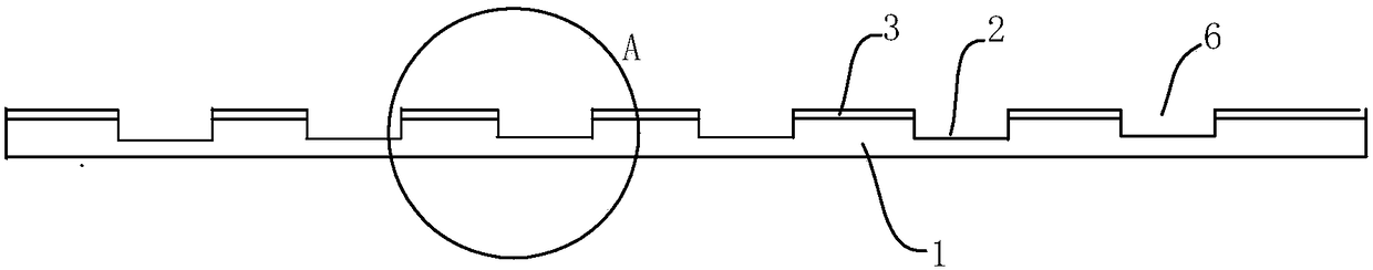
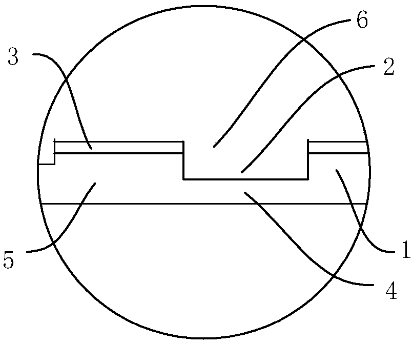
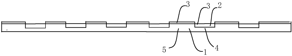
[0029] The principle of the present invention is to use laser to evenly distribute the grooves 2 on the diaphragm 1, the diaphragm 1 where the grooves 1 are located becomes thinner, and the ductility of the thinned diaphragm 1 increases, so that the central position and circumference of the diaphragm 1 The side position becomes loose at the same time, which effectively achieves the effect of slow tension and reduces the initial stress of the diaphragm, so that the entire vibration system has sufficient elasticity during energy conversion, thereby improving the tone of the diaphragm. Such as Figure 10 and Figure 11 As mentioned above, after adopting the technical solution of the present invention, the frequency response curve is obviously improved, and the timbre obtained by detection is obviously improved.

[0030] Such as Figure 1-Figur...


PUM


Abstract

The invention discloses a capacitive microphone diaphragm, a microphone and a production method thereof; the capacitive microphone diaphragm comprises a diaphragm and a metal film layer which is plated on the upper surface of the diaphragm. The capacitive microphone diaphragm is characterized in that a plurality of grooves are uniformly formed in the upper surface and / or the lower surface of the diaphragm; the diaphragm at the groove is a first diaphragm, the diaphragm at the periphery of the groove is a second diaphragm, and the thickness of the first diaphragm is smaller than that of the second diaphragm; the diaphragm, the microphone and the method have the advantage that the initial stress of the diaphragm is reduced, so that the whole vibration system has abundant elasticity during energy conversion; the induction of the diaphragm to the subtle sound is enhanced, the sensitivity of the diaphragm to the sound is increased, and the tone of sound input is finally improved; meanwhile,due to the fact that the tightening degree of the diaphragm is reduced, the service life and the reliability of the microphone are improved.

Description

technical field [0001] The invention relates to the field of electroacoustic equipment, in particular to a condenser microphone diaphragm, a microphone and a production method. Background technique [0002] Microphones, also known as microphones, can be divided into dynamic microphones, condenser microphones and ribbon microphones according to their working principles. Condenser microphones use a very thin metal diaphragm as the first stage of the capacitor, and another very close metal back plate (about a few tenths of a millimeter) as the other pole, so that the vibration of the diaphragm will cause changes in the capacitance to form electric signal. Because the diaphragm is very thin, even a very small sound can make it vibrate, so the condenser microphone is very sensitive. The biggest feature of the condenser microphone is its high sensitivity, rich details, and a flat and wide frequency response curve. [0003] The conventional diaphragm adopts a flat plate structure...

Claims


Application Information

Patent Timeline
Patent Type & Authority Applications(China)
IPC IPC(8): H04R7/12H04R19/04H04R31/00
CPCH04R7/12H04R19/04H04R31/003
Inventor 周代军
Owner 周代军
Why Eureka
Try Eureka