Radiator with rotation-speed indication function

A technology of heat dissipation device and speed, which is applied in the cooling of instruments, parts of instruments, cooling/ventilation/heating transformation, etc., which can solve the problem of inability to monitor the speed of fan modules.

Inactive Publication Date: 2007-11-21
HONG FU JIN PRECISION IND (SHENZHEN) CO LTD +1
View PDF0 Cites 2 Cited by
  • Summary
  • Abstract
  • Description
  • Claims
  • Application Information

AI Technical Summary

Problems solved by technology

[0004] However, it is generally difficult to directly observe and judge the speed of the fan module with the naked eye. Usually, the corresponding software can be used to monitor the speed of the fan module on the display screen. When there is no display screen or no corresponding software , it is impossible to monitor the speed of the fan module

Method used


Image

  • Radiator with rotation-speed indication function
  • Radiator with rotation-speed indication function
  • Radiator with rotation-speed indication function

Examples


Embodiment Construction

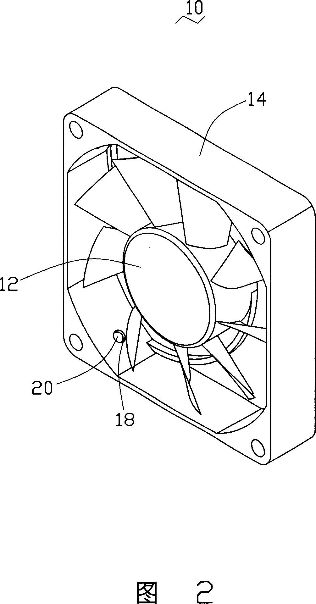
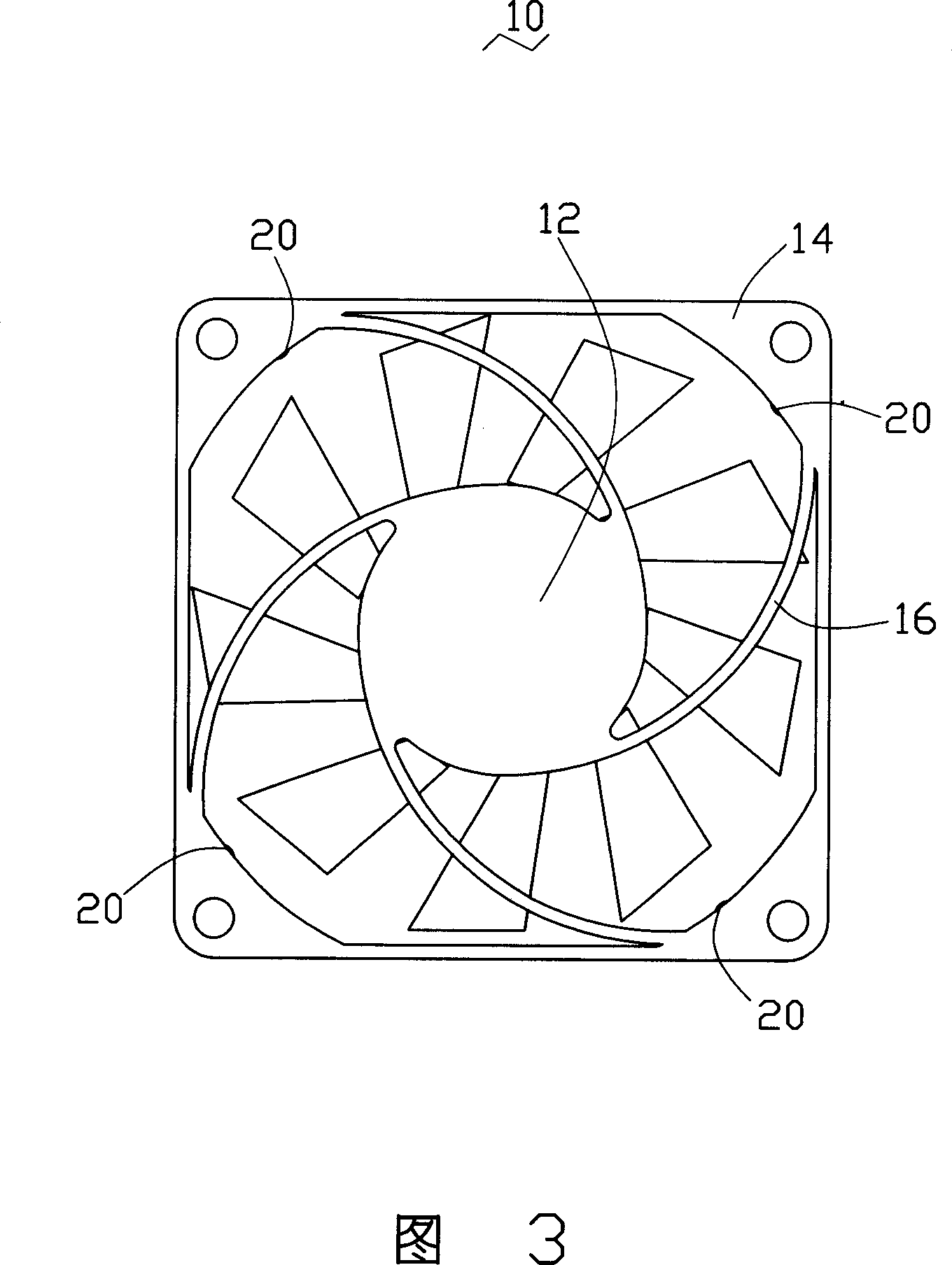
[0013] Please refer to FIG. 2 and FIG. 3 together. The preferred embodiment of the heat dissipation device with speed indicating function of the present invention is described by taking a fan module 10 as an example. The fan module 10 includes a fan 12 and a fan for supporting the The square outer frame 14 of the fan 12 is connected and supported by four arc-shaped ribs 16 to support the fan 12 .

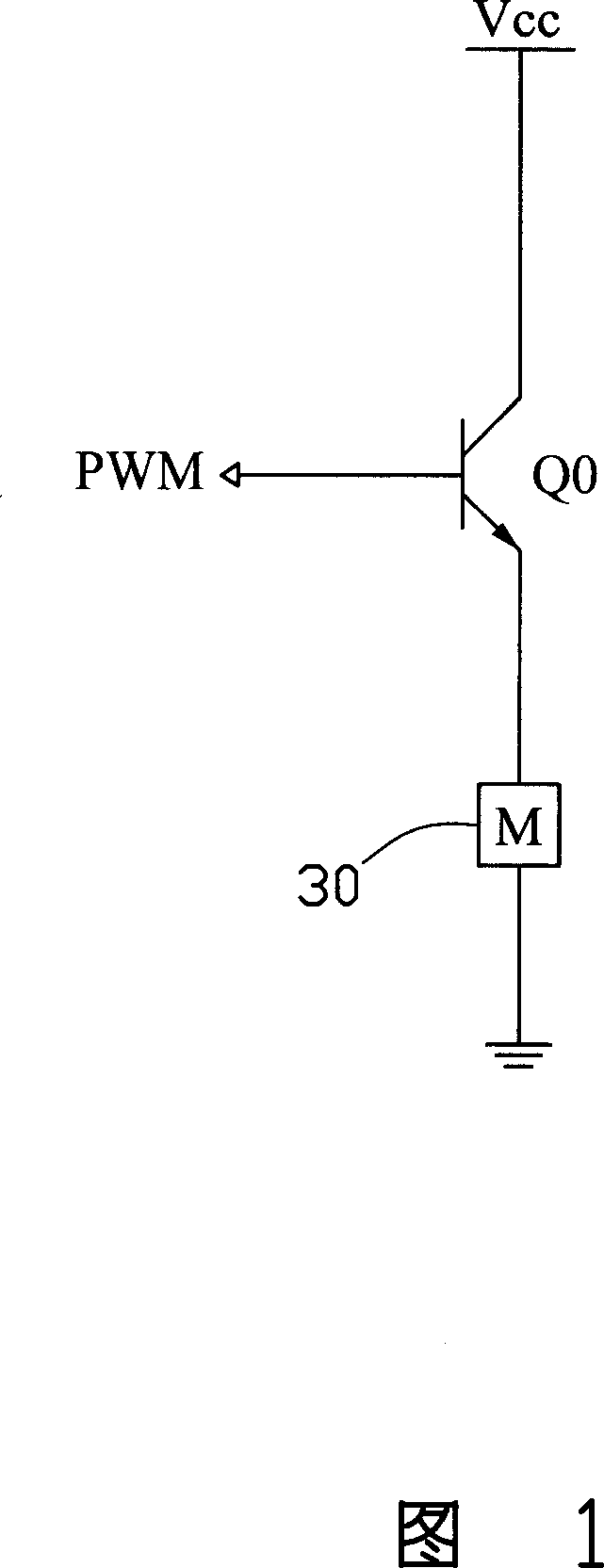
[0014] The four corners of the outer frame 14 are symmetrically provided with an installation hole 18, and each installation hole 18 is equipped with a light-emitting diode 20, the rib 16 is hollow, and the light-emitting diode 20 passes through the The wires (not shown) provided in the ribs 16 are connected with the internal circuit of the fan 12 . The light emitting diode 20 can be replaced by other indicator lights, and the number of the light emitting diode 20 can also be set according to specific needs, at least one. The colors of the light emitting diodes 20 can also be desig...


PUM


Abstract

The invention comprises: a fan; a fan-speed control circuit and a fan-speed indication circuit; said fan-speed indication circuit comprises a filter unit, a voltage-controlling unit, at least one indication lamp and a diode corresponding to the indication lamp; said fan-speed control circuit outputs an indication signal to ground via the filter unit and voltage control unit; the cathode of said diode is connected to the filter unit and the voltage control unit, and the anode of said diode is connected to the anode of the indication lamp; the cathode of the indication lamp is grounded.

Description

technical field [0001] The invention relates to a heat dissipation device, in particular to a heat dissipation device with a rotating speed indicating function. Background technique [0002] At present, most of the fan modules of the heating element (such as the central processing unit) in the existing computer mainframe are designed to change the speed of the heating element accordingly according to the temperature change of the heating element, so as to provide the heating element reasonably and effectively. Heat dissipation. [0003] As shown in Figure 1, it is a speed control circuit diagram of a fan module on a computer motherboard, the ground terminal of the motor 30 of the fan module is grounded, and the power supply terminal is connected to the emitter of a transistor Q0 with switching function. The collector of Q0 is connected to a DC power supply Vcc, the base of the transistor Q0 receives a PWM (Pulse Width Modulation, pulse width modulation) signal, and the spee...

Claims


Application Information

Patent Timeline
Patent Type & Authority Applications(China)
IPC IPC(8): H05K7/20H01L23/467G06F1/20G12B15/04F04C28/00
CPCH01L2924/0002
Inventor 孙正衡
Owner HONG FU JIN PRECISION IND (SHENZHEN) CO LTD
Why Eureka
Try Eureka