Fuel injection control device for internal combustion engine
A technology of fuel injection and control device, applied in the directions of fuel injection control, engine control, internal combustion piston engine, etc., can solve the problems of longer time, incorrect ignition sequence, etc., and achieve the effect of shortening the consumption time
- Summary
- Abstract
- Description
- Claims
- Application Information
AI Technical Summary
Problems solved by technology
Method used
Image
Examples
no. 1 approach
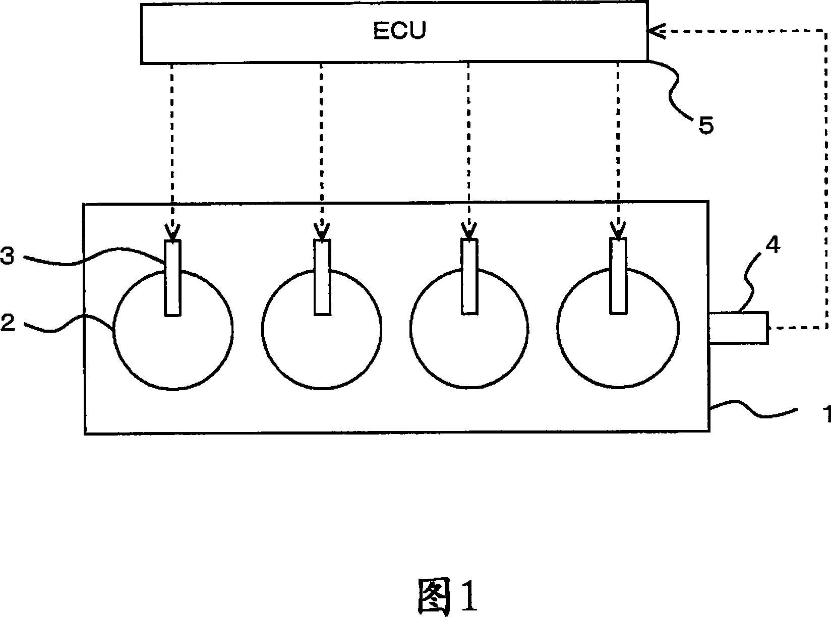
[0075] FIG. 1 is a schematic configuration diagram of an internal combustion engine 1 according to the present embodiment.
[0076] The internal combustion engine 1 shown in FIG. 1 is a four-stroke cycle water-cooled diesel engine with four cylinders 2 .
[0077] A fuel injection valve 3 that injects fuel into each cylinder 2 is provided in each cylinder 2 of the internal combustion engine 1 .
[0078] Furthermore, a crank position sensor 4 that outputs a signal depending on the engine speed is provided in the internal combustion engine 1 .
[0079] Furthermore, an ECU 5 as an electronic control unit for controlling the internal combustion engine 1 is provided together with the internal combustion engine 1 . The ECU 5 is a unit that controls the operating state of the internal combustion engine 1 according to the operating conditions of the internal combustion engine 1 and the driver's request.
[0080] Fuel injection valve 3 is connected to ECU 5 by wires, and ECU 10 contro...
no. 2 approach
[0121] In this embodiment, compared with the first embodiment, the set value of the fuel injection timing in the next stroke cycle of the cylinder that has misfired is different. Other than that, the hardware is the same as that of the first embodiment, so the description thereof is omitted.
[0122] Here, unburned fuel remains in the misfiring cylinder, and in the next stroke cycle, this unburned fuel promotes the ignition of the fuel. In addition, the ignition lag during fuel ignition becomes short due to unburned fuel remaining in the cylinder. Thus, in the misfired cylinder, the ignitability in the stroke cycle following the misfire stroke cycle is improved.
[0123] Fig. 9 is a combustion state diagram of the next stroke cycle of each combustion state. The engine speed is shown on the abscissa and the ignition lag is shown on the ordinate. An ignition lag of 40° CA indicates that ignition did not occur (ie misfire occurred). In addition, a triangular symbol indicates ...
no. 3 approach
[0140] In the third embodiment, the fuel injection timing is set based on the history of past combustion states. Other than that, hardware is the same as that of the first embodiment, and thus description thereof will be omitted.
[0141] Here, during start-up of the internal combustion engine, since ignitability is prioritized, the fuel injection timing is set to the advanced side in all cylinders. Furthermore, the increase in engine speed is achieved by gradually retarding the fuel injection timing from the start of the internal combustion engine.
[0142] Furthermore, in this embodiment, during the period from the start of the internal combustion engine to the completion of the start, the accumulated number of ignition failures or the accumulated number of ignitions for each cylinder from the start to the current point in time is obtained, and based on this value, The delay amount of the fuel injection timing from the current point of time to the start completion is change...
PUM
 Abstract
Description
Claims
Application Information
 - R&D
- Intellectual Property
- Life Sciences
- Materials
- Tech Scout
- Unparalleled Data Quality
- Higher Quality Content
- 60% Fewer Hallucinations
Browse by: Latest US Patents, China's latest patents, Technical Efficacy Thesaurus, Application Domain, Technology Topic, Popular Technical Reports.
© 2025 PatSnap. All rights reserved.Legal|Privacy policy|Modern Slavery Act Transparency Statement|Sitemap|About US| Contact US: help@patsnap.com


