Novel technics of metallurgy mineral dressing flotation air inflation and special equipment

A special equipment, mineral flotation technology, applied in flotation, solid separation and other directions, can solve the problem that the effective volume of a single machine cannot keep up with the development needs, reduce the speed of mineral leaching/oxidation, and reduce the cut-off grade of useful minerals. Save power consumption, improve flotation recovery rate, and realize the effect of automatic control

Inactive Publication Date: 2007-12-05
王树芳
View PDF0 Cites 17 Cited by
  • Summary
  • Abstract
  • Description
  • Claims
  • Application Information

AI Technical Summary

Problems solved by technology

[0002] At present, with the expansion and sharp increase of mineral development and utilization, the cut-off grade of useful minerals has decreased. In order to obtain more useful minerals, the scale of ore dressing plants has become larger and larger. However, no major improvements and breakthroughs have been made in terms of stirring the pulp and aeration methods. The effective volume of a single machine cannot keep up with the development needs, the flotation effect is not good, and the power consumption is large.
For example, the inflating method of the leaching tank / oxidation tank in the existing non-ferrous metal beneficiation and smelting plant is generally to insert several steel pipes to inflate. Oxidation rate, which affects the improvement of leaching / oxidation recovery

Method used


Image

  • Novel technics of metallurgy mineral dressing flotation air inflation  and special equipment
  • Novel technics of metallurgy mineral dressing flotation air inflation  and special equipment
  • Novel technics of metallurgy mineral dressing flotation air inflation  and special equipment

Examples


Embodiment 1

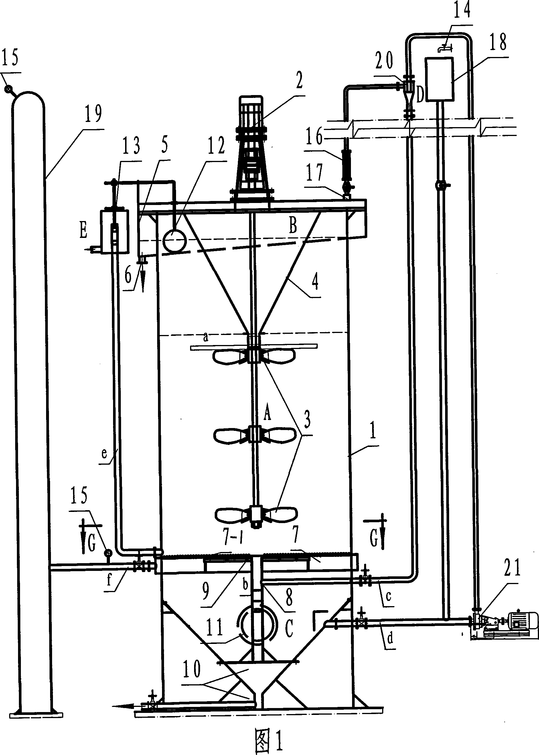
[0020] Embodiment 1, as shown in Fig. 1-Fig. 3, the device is mainly composed of host machine A, foam overflow system B, microbubble generating separator, microbubble generating system D and automatic liquid level pulp regulating mechanism E, etc. in,

[0021] The main engine A includes a stirring tank body 1, on which a reduction device 2 composed of a motor and a vertical reducer is installed, and an upper, middle and lower three-layer worm impeller stirring paddle 3 is installed in the stirring tank body 1, wherein The uppermost worm impeller agitator 3 is additionally equipped with a flat column pulp distribution blade a, and the worm impeller agitator 3 is connected to the reduction device 2 through a shaft;

[0022] The foam overflow system B is set in the main machine A, and includes a foam-push inverted cone-shaped tank 4 installed on the upper part of the stirring tank 1, and an annular foam overflow chute 5 is arranged on the upper end of the foam-push inverted cone-...

Embodiment 2

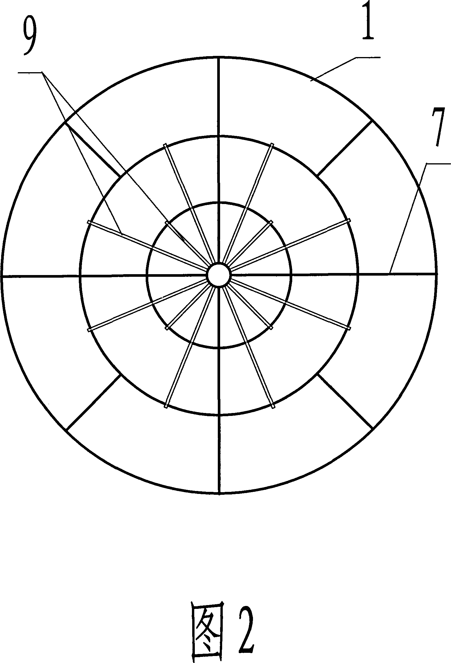
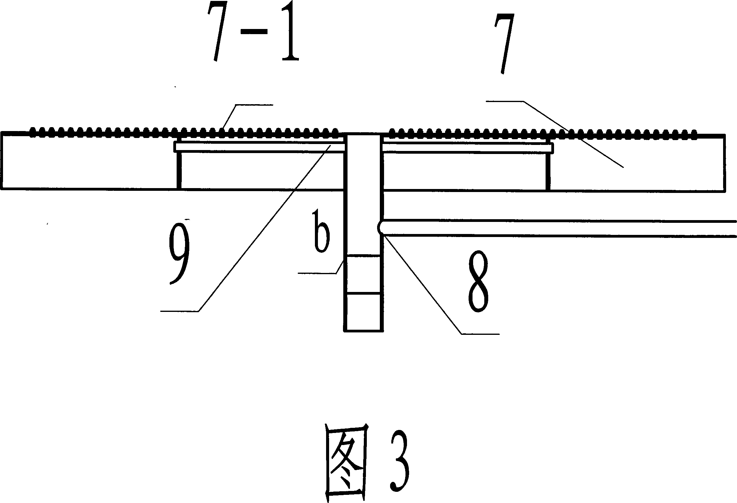
[0034] Embodiment 2, referring to Fig. 4, the structure of this example is basically the same as that of the previous example, the difference is that instead of using the water pump 21 and the vacuum water jet pump 20, the air can be directly supplied by the air compressor, and the air passes through the air inlet 17 , air flow meter 16, air supply pipe c, enter the air-water separation column tube 8, and then pass through some inflation distribution branch pipes 9, enter in each chamber of the microbubble inflation distributor 7, overflow from the inflation micropore 7-1, To achieve the purpose of microbubble inflation.

[0035]The present invention adopts the above-mentioned device to realize complete coverage of micro-bubble inflation with no dead angle, good inflation effect, high flotation recovery rate, sufficient oxidation reaction, higher and faster leaching speed, and achieves the purpose of strengthening oxidation leaching and improving recovery rate, and It can be f...


PUM


Abstract

The present invention discloses inflated metallurgical floatation process and apparatus, and features the completely covered microbubble inflating in the self balanced water separated microbubble generating and inflating mode. The apparatus includes a main machine, a bubble overflowing system, a microbubble generating separator, a microbubble generating system, an automatic mineral slurry regulating mechanism to control the liquid level, etc. Inside the floatation column, leaching tank and oxidation tank, great amount of microbubbles are generated in the bottom and flown in the opposite direction to the falling mineral slurry so as to raise the stirring effect, form stable floating bubble layer, speed oxygen dissolution, increase oxygen utilizing rate, enhance oxidizing leaching and raise floatation recovering rate.

Description

technical field [0001] The present invention relates to a new micro-bubble aeration process of three-impeller agitation flotation column / leaching tank / oxidation tank, specifically a new aeration process and special equipment for metallurgical dressing flotation Column / leaching tank / oxidation tank) for microbubble aeration, which belongs to metallurgical technology. Background technique [0002] At present, with the expansion and sharp increase of mineral development and utilization, the cut-off grade of useful minerals has decreased. In order to obtain more useful minerals, the scale of ore dressing plants has become larger and larger. However, no major improvements and breakthroughs have been made in terms of stirring the pulp and aeration methods. The effective volume of a single machine cannot keep up with the development needs, the flotation effect is not good, and the power consumption is large. For example, the inflating method of the leaching tank / oxidation tank in t...

Claims


Application Information

Patent Timeline
Patent Type & Authority Applications(China)
IPC IPC(8): B03D1/02B03D1/16
Inventor 王树芳王英秋
Owner 王树芳
Why Eureka
Try Eureka