Method for measuring transmissivity relevant frequency spectrum method grain and device thereof

A measurement method and transmittance technology, which are used in transmittance measurement, special data processing applications, complex mathematical operations, etc., and can solve problems such as inability to measure particles above micron level and inability to achieve online measurement.

Inactive Publication Date: 2007-12-05
UNIV OF SHANGHAI FOR SCI & TECH
View PDF3 Cites 20 Cited by
  • Summary
  • Abstract
  • Description
  • Claims
  • Application Information

AI Technical Summary

Problems solved by technology

[0003] The purpose of the present invention is to solve the technical problem that the PCS method cannot be used to measure particles above the micron level and cannot realize online measurement, and to provide a method and device for measuring particle size distribution, concentration and velocity by using the transmittance pulsation correlation spectrum method

Method used


Image

  • Method for measuring transmissivity relevant frequency spectrum method grain and device thereof
  • Method for measuring transmissivity relevant frequency spectrum method grain and device thereof
  • Method for measuring transmissivity relevant frequency spectrum method grain and device thereof

Examples


Embodiment 1

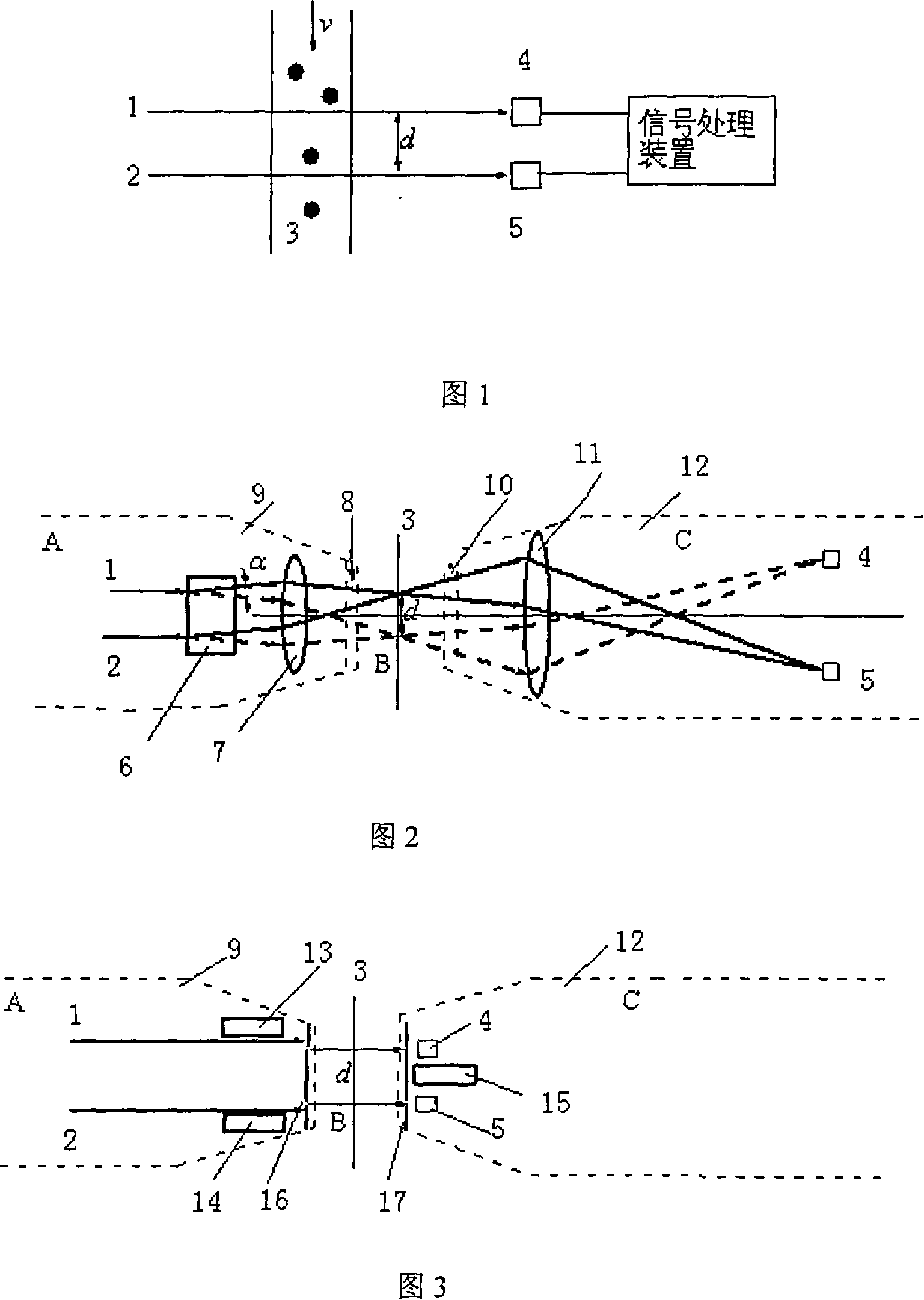
[0056] As shown in Figure 2, the measuring device is composed of a measuring area, a narrow beam generator, a photoelectric signal detector and a signal receiving and processing device. It consists of parallel light beams 1 and 2 emitted by a laser, which are split by a beam splitter 6 and then converged by a convex lens 7 (or lens group). The Rayleigh zone near the focal point results in a narrow beam of approximately parallel light. The transmitted light is two divergent Gaussian beams, which are converged to the respective photodetectors 4 and 5 through the receiving lens 11, which requires high time sensitivity of the measuring device. Air-blown window antifouling devices 8, 10, 9, 12 are respectively arranged at the transmitting end and the signal receiving end as the shells of the transmitting end A and the signal receiving end C respectively. This structure is a probe structure.

Embodiment 2

[0058] As shown in Figure 3, the composition of the measuring device is the same as that of Embodiment 1. The narrow beam generator is composed of a laser that generates parallel beams and one or both of the porous diaphragms or optical fiber groups that are arranged at the optical signal transmitting end and the optical signal receiving end, and the wide beam emitted by the laser A set of porous diaphragms or optical fibers arranged in the direction of propagation results in a set of narrow beams. The parallel light beams 1 and 2 pass through the porous diaphragm 16 at the window and take out the narrow beam group to enter the measurement area 3. The positions of the narrow beams are placed successively along the particle flow direction. After the signal light enters the receiving end C, it irradiates the respective photoelectric signal detectors 4 and 5 through the aperture 17, which requires high time sensitivity of the photoelectric signal detectors. Air-blown window anti...

Embodiment 3

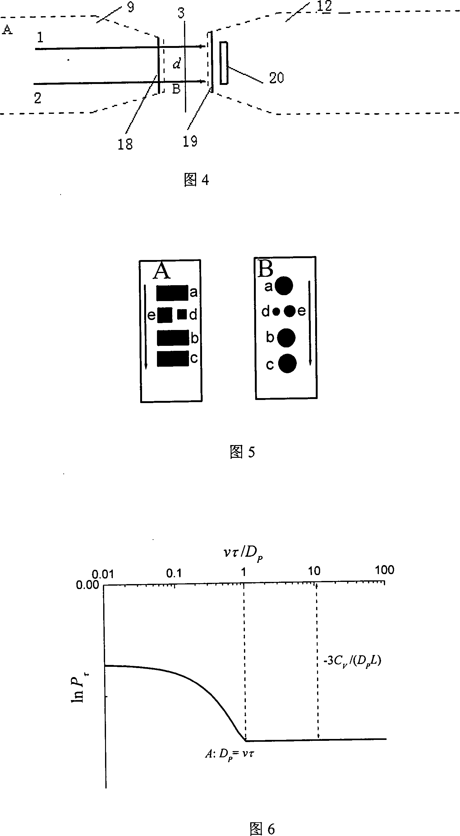
[0060] The measuring device shown in Figure 3 can be made into a probe form or a split-type on-line measuring device, and its composition is also the same as in Embodiments 1 and 2. The narrow beam generator is composed of lasers and microelements that generate parallel beams. The signal detector is composed of parallel light beams 1 and 2 emitted by the laser and directly irradiated to the micro-element photodetector 20 through the measurement area 3. The micro-element photodetector 20 is not only used as a photoelectric signal detection unit, but also as a narrow beam generator. Composition components, 18 and 19 in the figure are air-blown anti-fouling devices, the micro-element photodetector: it is composed of a plurality of photodetection units (made of silicon light film material) with small light-receiving areas, and each unit The shape can be circular or polygonal (such as rectangle, hexagon, etc.), this combination is conducive to the proper placement of the relative po...


PUM

PropertyMeasurementUnit
lengthaaaaaaaaaa
lengthaaaaaaaaaa

Abstract

The invention discloses a kind of particle measurement method about penetration ratio relation spectrum method and its equipment. It is characterized in that this invention uses of the impulsive signal characteristic of the particle penetration ratio signal of the particle shining under the sharp beam and treats the penetration ratio impulsive signal so it can get the particle velocity, the particle grain size distribution and the information of particle density. This method is named penetration ratio impulsive related spectrum method which adopts the light signal dynamic characteristic and the related treatment of signal. It can measure the particle grain size distribution, density, and velocity above micron class. The benefit effect of invention I that the measurement method and equipment are easy, low cost, and realizes the on-line and real-time detection and at the same time it realizes the test of particle grain size distribution, density, and velocity. It can be used in science study, the production of chemical energy and the course control, the protection of environment, the detection of water quality and the measurement of particle and so many fields.

Description

technical field [0001] The invention relates to a method and device for simultaneously measuring particle size distribution, concentration and velocity, in particular to a method and device for measuring particle size distribution, concentration and velocity by using the transmittance pulsation correlation spectrum method, which belongs to measurement technology field. The invention can measure many particle parameters and a wide range of particle diameters, and is suitable for on-line monitoring of particle-containing two-phase flow, and can be used for scientific research, chemical energy production and process control, environmental protection, water quality detection, etc. involving particle measurement. fields. Background technique [0002] Correlation processing of particle scattering light dynamic information has long been applied in the measurement technology of nanoparticles, which is called Photon Correlation Spectrometry (PCS for short). In the PCS method, the p...

Claims


Application Information

Patent Timeline
Patent Type & Authority Applications(China)
IPC IPC(8): G01N15/00G01N21/59G06F19/00G06F17/15
CPCY02A20/152
Inventor 沈建琪蔡小舒于彬
Owner UNIV OF SHANGHAI FOR SCI & TECH
Why Eureka
Try Eureka