
DC electric machine

A technology of DC motors and rotors, applied in the direction of electrical components, etc., can solve the problems of complex manufacturing of DC motors, restrictions on the application of DC motors, and persistent difficulties of DC motors, and achieve the effects of less magnetic flux leakage, compact size, and easy manufacturing and processing

Inactive Publication Date: 2007-12-05
石玉山
View PDF0 Cites 0 Cited by
  • Summary
  • Abstract
  • Description
  • Claims
  • Application Information

AI Technical Summary

Problems solved by technology

[0003] 1. This structure makes the DC motor must have a reversing device, and the problem of reversing is the "big problem" of the DC motor
[0004] 2. This structure makes the manufacture of DC motor complicated, expensive, bulky, long magnetic circuit, and consumes a lot of iron and copper.
Poor heat dissipation, low efficiency, high failure rate, difficult maintenance
[0005] 3. This structure limits the application of DC motors and can only be used in limited occasions

Method used


Image

  • DC electric machine
  • DC electric machine
  • DC electric machine

Examples


Embodiment Construction

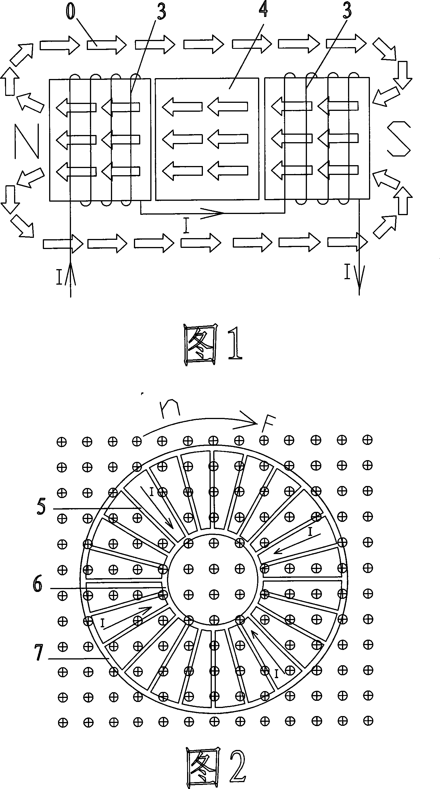
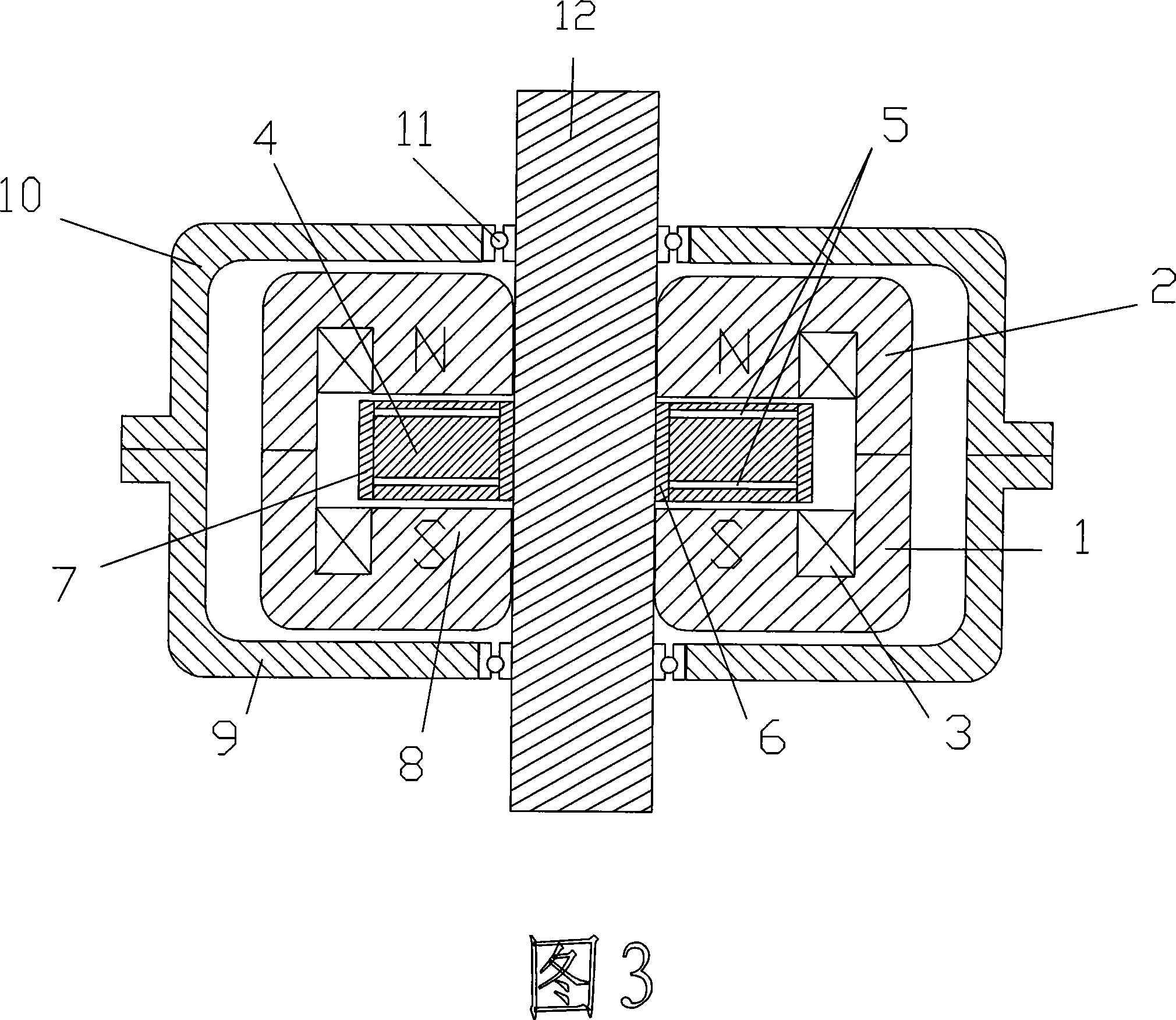
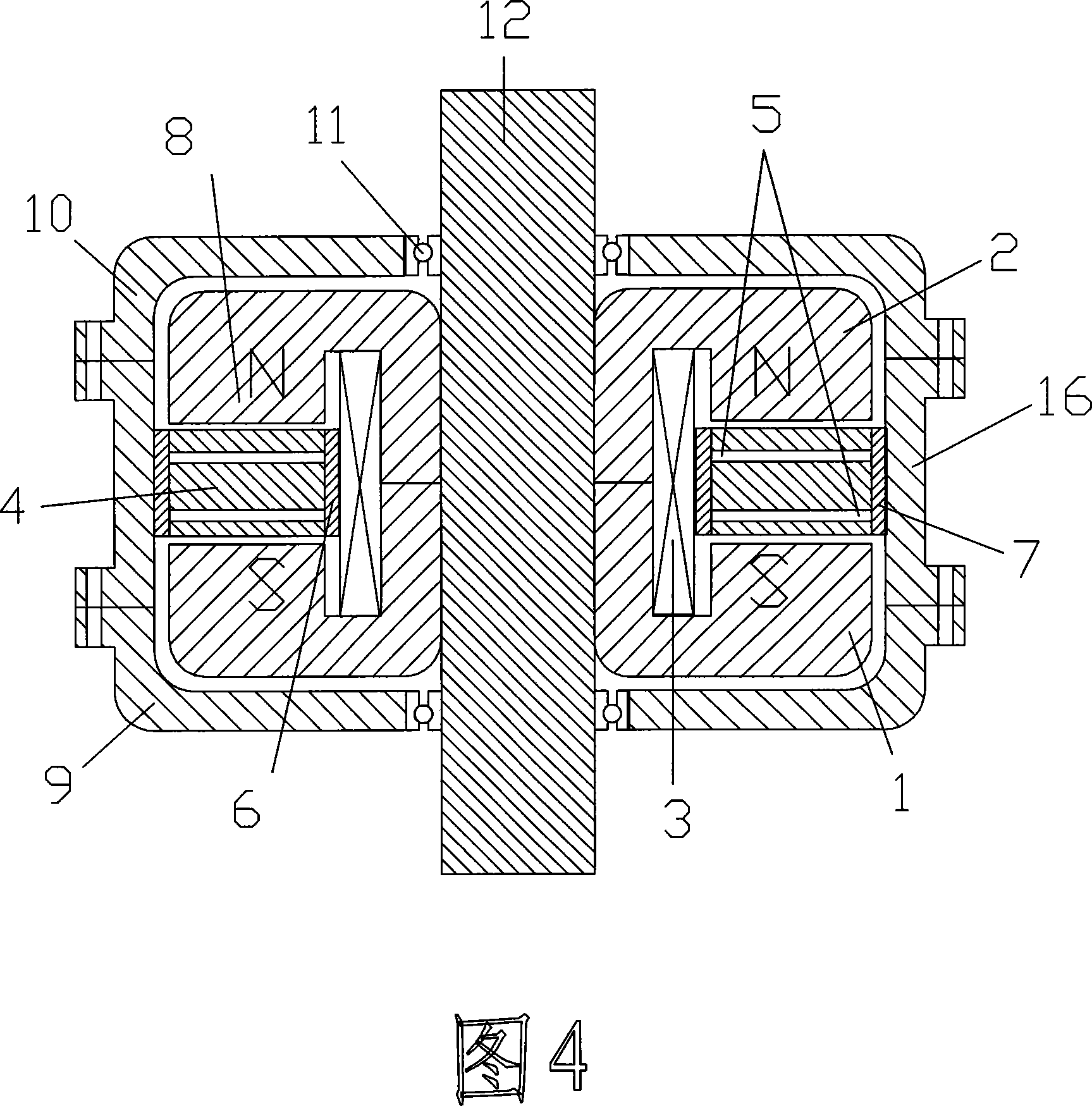
[0022] The DC motor of the present invention is different from ordinary motors in manufacture. Its key components, the rotor and the stator, are made of strip-shaped silicon steel sheets and are automatically completed by computer control on the iron core punching and coiling machine. Before that, open a set of molds for the rotor, and install the molds on the iron core punching and coiling machine. After the rotor and the stator are made, the front stator core (1) and the rear stator core (2) are put together again. The stator coils (3) are wound in one direction and are respectively mounted on the circular magnetic poles (8) of the front stator core (1) and the rear stator core (2). Front end cover (9), rear end cover (10) and support all are cast by pig iron or aluminum alloy. After forming, it can be processed on the machine tool.


PUM


Abstract

The invention is a communicator-free DC machine, relating to the electric machine field, and it comprises stator, rotor, coils, bearings, rotating shaft, and machine end cover; its rotating magnetic field is in parallel with its rotating shaft, and it uses at most two excitation coils and has only one pair of magnetic poles, i.e N pole and S pole and does not use any communicator; the rotor of an inner rotor DC machine is a low and thick, solid, circular rotor contained by two stators; the rotor of an outer rotor DC machine is a low and thick, solid, circular rotor placed between two stators. And this machine consumes few materials, easy to make, has good ventilating and heat radiating effects, high operating efficiency and low failure ratio, simple and convenient to maintain, and able to meet requirements of application fields in large range.

Description

Technical field: [0001] The invention relates to the field of electrical machines. Background technique: [0002] For more than one hundred years, conventional DC motors are structurally composed of casings, bearings, rotors, stators, commutators, carbon brushes, armature components and numerous field windings. The magnetic field lines doing work are perpendicular to the motor shaft. This structure creates the following common insurmountable flaws: [0003] 1. This structure makes the DC motor must have a reversing device, and the problem of reversing is the "big problem" of the DC motor. [0004] 2. This structure makes the DC motor complex to manufacture, expensive to manufacture, bulky, long magnetic circuit, and consumes a lot of iron and copper. The heat dissipation is not good, the efficiency is not high, the failure rate is high, and the maintenance is difficult. [0005] 3. This structure limits the application of the DC motor and can only be used in limited occa...

Claims


Application Information

Patent Timeline
Patent Type & Authority Applications(China)
IPC IPC(8): H02K57/00
Inventor 石玉山
Owner 石玉山
Learn More