Electronic device and heat radiating module

A heat dissipation module and electronic device technology, which is applied in the direction of circuits, electrical components, electric solid devices, etc., can solve the problems of unable to dissipate heat from FB-DIMM, reduced airflow intensity, limited internal space of the host, etc., and achieve the best heat dissipation effect

Active Publication Date: 2007-12-05
ASUSTEK COMPUTER INC
View PDF0 Cites 10 Cited by
  • Summary
  • Abstract
  • Description
  • Claims
  • Application Information

AI Technical Summary

Problems solved by technology

[0008] However, there are usually many power cables or boards such as RAID Cards inside the host computer, so the airflow generated by the system fan will be affected by the flow resistance of the power cables or boards, and cannot be convected. FB-DIMM, so that it may not be able to effectively dissipate heat from the FB-DIMM
[0009] In addition, due to the limited internal space of the host, it is not easy to have enough space i

Method used


Image

  • Electronic device and heat radiating module
  • Electronic device and heat radiating module
  • Electronic device and heat radiating module

Examples


Example Embodiment

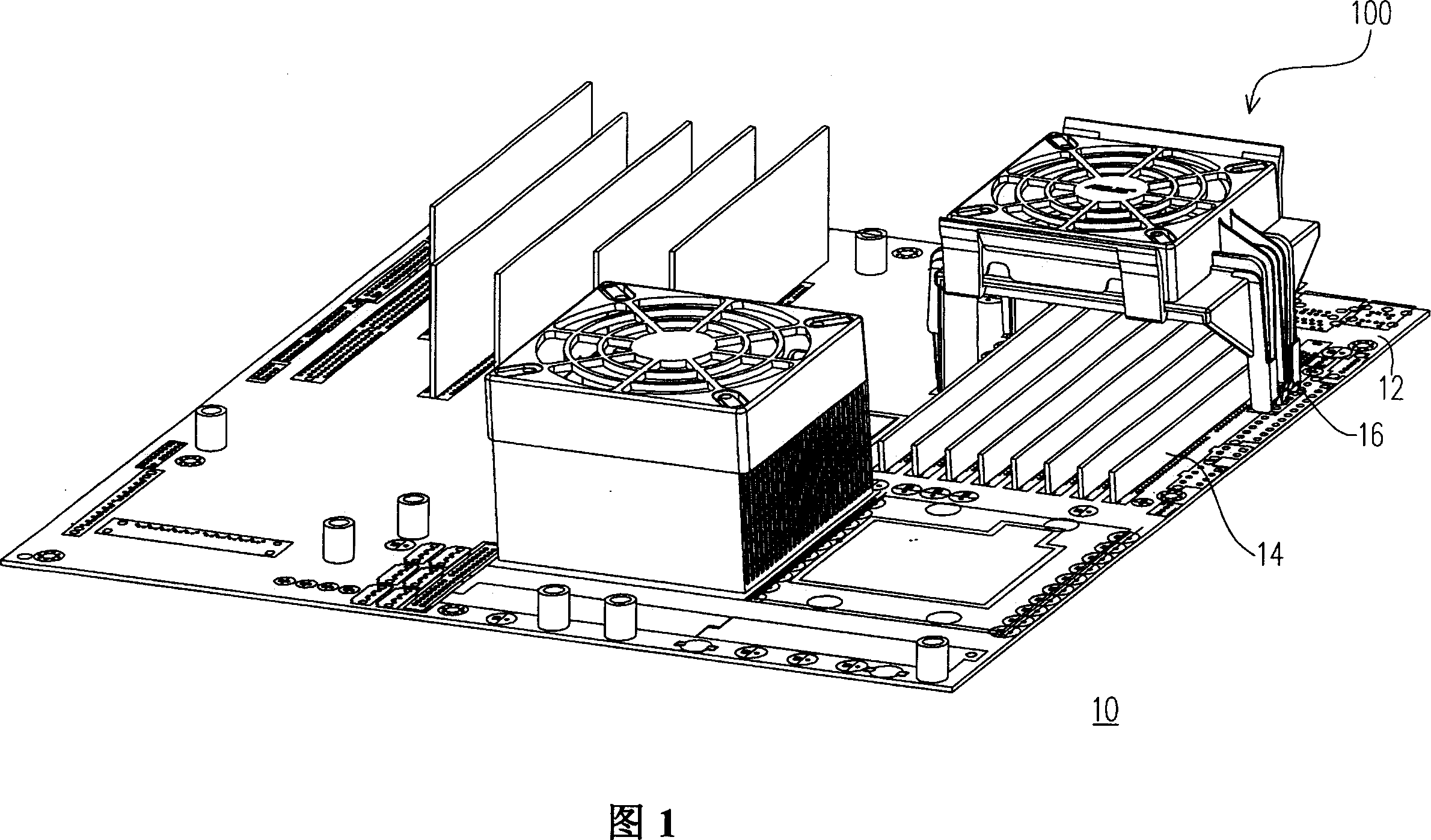
[0055]FIG. 1 is a schematic diagram of a heat dissipation module 100 assembled in an electronic device 10 according to a preferred embodiment of the present invention. 1, the heat dissipation module 100 of this embodiment is suitable for being assembled on the circuit board 12 of the electronic device 10 to dissipate heat from the heat source 14 on the circuit board 12. The heat dissipation module 100 is clamped around the heat source 14 The multiple engaging holes 16 are assembled on the circuit board 12.

[0056] In this embodiment, the electronic device 10 is a server. In other embodiments, the electronic device 10 may be a 2U disk array (RAID) device or a computer device host. In addition, in this embodiment, the heat source 14 is a plurality of memory modules, and these memory modules are preferably fully buffered memory modules (FB-DIMM). In other embodiments, the heat source 14 may also be a Northbridge chip, Graphics chip, RAID card, or other system chip set in the server....


PUM


Abstract

The present invention is a heat-scattered module used for being assembled onto the several locking holes on circuit boards and distributing heats of heat sources on circuit boards. The heat-scattered module includes a bearing frame, a fan and a covering part. The bearing frame is composed of bearing base and several first footings extending downward from the bearing base. Every first footing has a elastic locking part for locking in the locking holes, and the elastic locking part has a containing space. In addition, the fan is assembled on the bearing base, and the covering part covers the fan and is assembled on the bearing base. The covering part is composed of a casing and several second footings, in which the casing is used for covering the fan, and the second footings extend downward from the casing relative to the first footings. The side away from the casing of every second footings has a tenon inserted in the containing space.

Description

technical field [0001] The invention relates to a heat dissipation module, in particular to an electronic device and a heat dissipation module thereof. Background technique [0002] With continuous breakthroughs in semiconductor technology, the volume of integrated circuit (Integral Circuit, IC) components is getting smaller and smaller, and the operation speed is getting faster and faster. When the circuit is running, the temperature of the electronic components will rise, especially when the operation speed of the IC components is higher, the heating will become more serious. Among the IC components used in computer hardware, multiple IC components are often combined into a chip module to perform certain functions. Due to the high operating temperature, the IC components may malfunction or even be destroyed. Therefore, how to reduce the IC component Working temperature becomes a very important issue. [0003] For example, in a server (server), usually a plurality of memo...

Claims


Application Information

Patent Timeline
IPC IPC(8): H05K7/20H01L23/467G06F1/20G12B15/04
Inventor 陈建印
Owner ASUSTEK COMPUTER INC
Why Eureka
Try Eureka