
Partial radiation cooling device

A radiant refrigeration and partial technology, applied in refrigerators, refrigeration components, refrigeration and liquefaction, etc., can solve the problems of induced discomfort, discomfort, and short service life, so as to maintain comfort, prevent condensation, prevent The effect of increasing the temperature deviation

Inactive Publication Date: 2007-12-19
SAMHWA CO LTD
View PDF0 Cites 9 Cited by
  • Summary
  • Abstract
  • Description
  • Claims
  • Application Information

AI Technical Summary

Problems solved by technology

[0004] First, contamination and microbial growth occur on the surface of the thermal evaporator due to the dew condensation phenomenon of the evaporator
The release of microorganisms through the air is not only a health hazard, but also the odor emitted from the evaporator while starting the air reduces the comfort in the room
[0005] Second, because it is a forced convection type and has a large capacity, when the cold air flow is directly blown to people by convection, it will not only induce a cold draft, but also cause air conditioning problems in the case of excessive cooling. side effects such as headache
[0006] Third, in Korea, the actual situation of the use of refrigerators is that the annual operating time is only 20 to 30 hours, and it is concentrated in summer, but the capacity of forced convection type refrigerators is too large, and there is a problem that the use period is too short. question
[0017] However, in the above-mentioned radiant ceiling panel system, condensation frequently occurs on the surface of the panel installed on the ceiling, and especially in the domestic climate where the refrigerant is used in summer, the temperature is high and humidity is high. Therefore, there are the following problems: The greater the possibility of condensation forming on the surface of the radiant panel, the higher the possibility of microorganisms multiplying on the surface of the radiant panel
[0018] In addition, since the radiation panel is installed on the ceiling, the dew falling from the junction directly touches the human body, causing a problem of causing discomfort

Method used

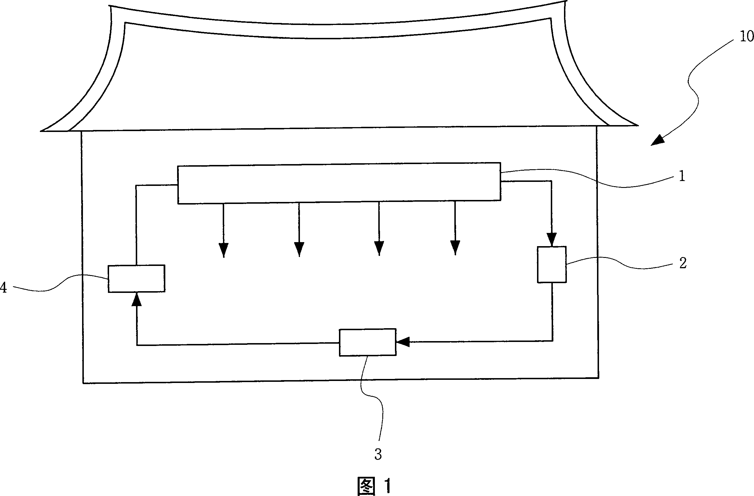

Image

  • Partial radiation cooling device
  • Partial radiation cooling device
  • Partial radiation cooling device

Examples


Embodiment Construction

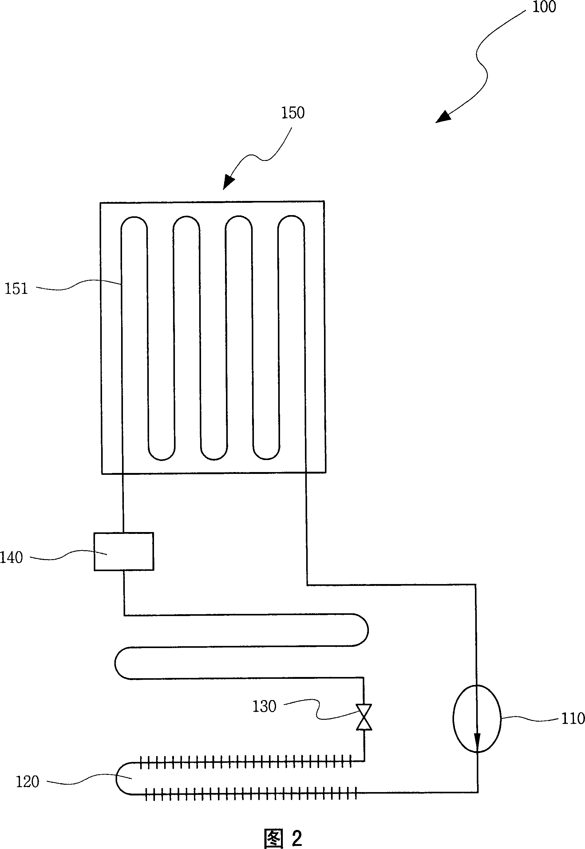
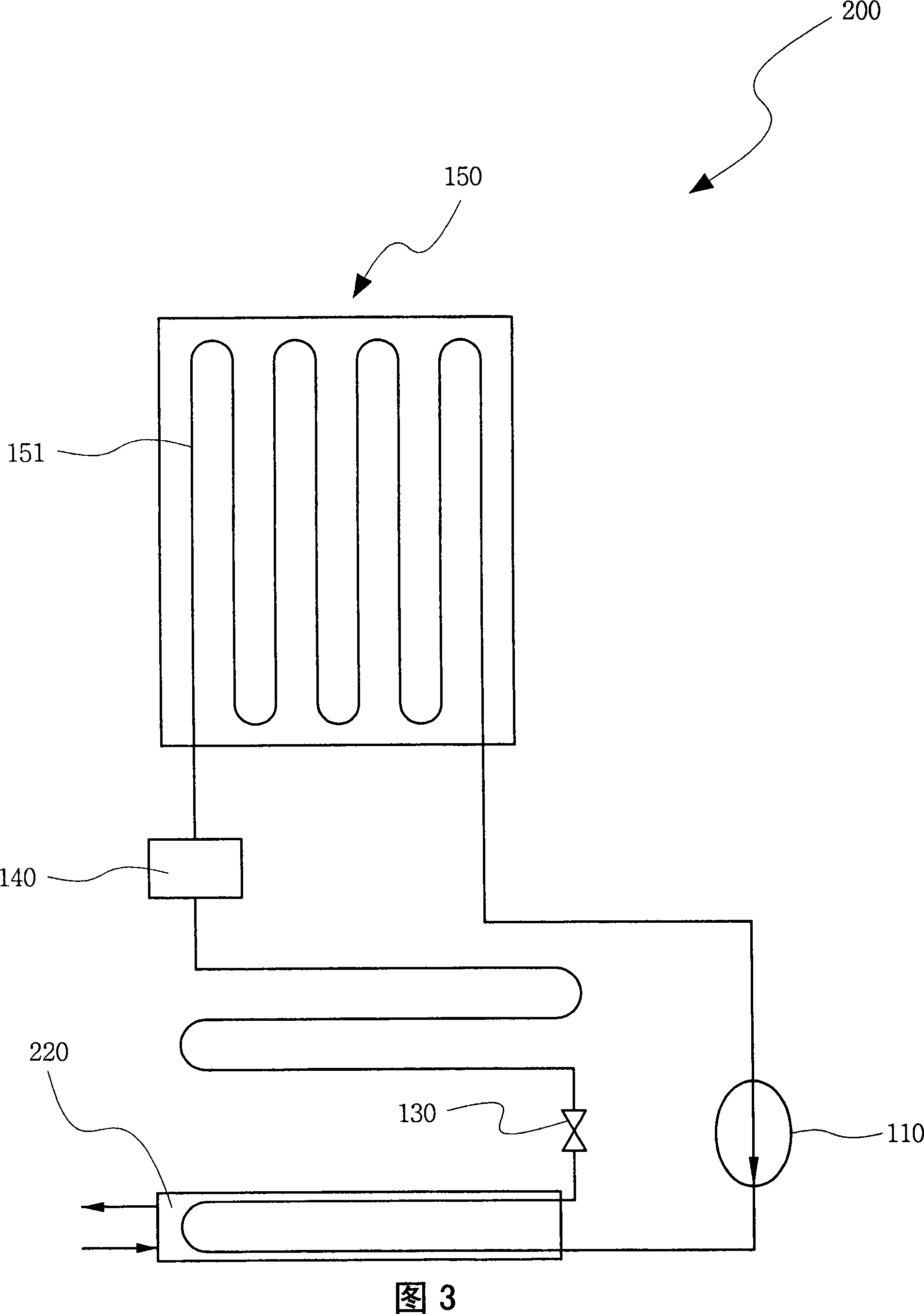
[0042] The local radiant refrigeration device of the present invention can be roughly classified into direct expansion type and indirect cooling type.

[0043] The direct expansion type is a direct cooling method in which the refrigerant is directly evaporated in the pipeline installed inside the radiant panel, and the indirect cooling type is to exchange heat between the refrigerant and the second refrigerant to make it undergo a one-time evaporation process, and then The indirect cooling method is an indirect cooling method in which the second refrigerant cooled by heat exchange is passed through a pipe provided inside the radiant panel to cool it.

[0044] First, the direct expansion radiant refrigeration device in an embodiment of the present invention is as follows.

[0045] Fig. 2 is the accompanying drawing that shows the direct expansion type partial radiation refrigeration device of the first embodiment of the present invention, Fig. 3 is the accompanying drawing that...


PUM


Abstract

The present invention provides a partial radiation refrigerating device which includes the following components: a compressor which does adiabatic compression to the vaporing refrigerant and discharges it with the high temperature and high pressure refrigerant air form; a condenser which extracts condensing latent heat from the high temperature and high pressure refrigerant gas and changes it to the high temperature and high pressure liquid refrigerant; an expansion valve which uses the throttling expansion to switch the high temperature and high pressure liquid refrigerant to refrigerant with low temperature and low pressure state; a radiation panel which includes an evaporator, the inner side of the evaporator is formed with a pipeline with which the low temperature and low pressure liquid refrigerant gets through, make the liquid evaporate and extract the surrounding heat; and a dehumidifying part which eliminates the moisture in the indoor air to avoid the moisture condensation on the radiant panel. The partial radiation refrigerating device according to the structure prevents the moisture condensation on the surface of the radiant panel and can refrigerate partially, it can be moved and it can keep the comfortable feeling at the condition of high moisture capacity.

Description

technical field [0001] The present invention relates to radiant cooling devices, in particular to localized radiative cooling devices utilizing radiant panels. Background technique [0002] At present, the evaporator of an air conditioner that is mostly used as a summer refrigerator is a forced convection type thermal evaporator (Forced convection) in which a blower sends air to a cooling coil attached to an aluminum pin and passes it through to perform heat exchange. [0003] The forced convection heat evaporator type refrigerating machine as described above is excellent in heat conduction, but involves problems as described below. [0004] First, contamination and microbial growth occur on the surface of the thermal evaporator due to the dew condensation phenomenon of the evaporator. The release of microorganisms through the air is not only a health hazard, but the odors emitted from the evaporator while the air is being activated reduce the comfort in the room. [0005]...

Claims


Application Information

Patent Timeline
IPC IPC(8): F24F3/14F25B1/00
CPCF25B40/02F25B47/006F25B2339/0241F25B41/31
Inventor 金学根
Owner SAMHWA CO LTD
Learn More