Terminal system

A terminal system, input and output technology, applied in general control systems, control/regulation systems, program control, etc., can solve the problems of complex wiring layout, multi-core cable wiring disconnection, wiring changes, etc., and achieve layout changes. It is easy to realize the effect of improving the number of wiring and reliability

Active Publication Date: 2007-12-26
ANYWIRE
View PDF2 Cites 4 Cited by
  • Summary
  • Abstract
  • Description
  • Claims
  • Application Information

AI Technical Summary

Problems solved by technology

[0005] In addition, in the above-mentioned wiring method, due to the increase in the amount of wiring, the space of the wiring duct will be enlarged. Disconnection of wiring and increase in maintenance time, and when there is a movable wiring part, problems such as disconnection of multi-core cable wiring occur
In addition, the life of the products using the above-mentioned wires is getting shorter and shorter. In order to improve the product, change the model, and change the product itself, it is necessary to change the layout. In these cases, the wiring layout is very complicated and difficult. It is difficult to reconfigure the shed and change the wiring, etc.

Method used


Image

  • Terminal system
  • Terminal system
  • Terminal system

Examples


Embodiment 1

[0146] Embodiments of the present invention will be described with reference to FIGS. 1 to 15 .

[0147] Fig. 1 shows a plurality of input and output systems in the present invention.

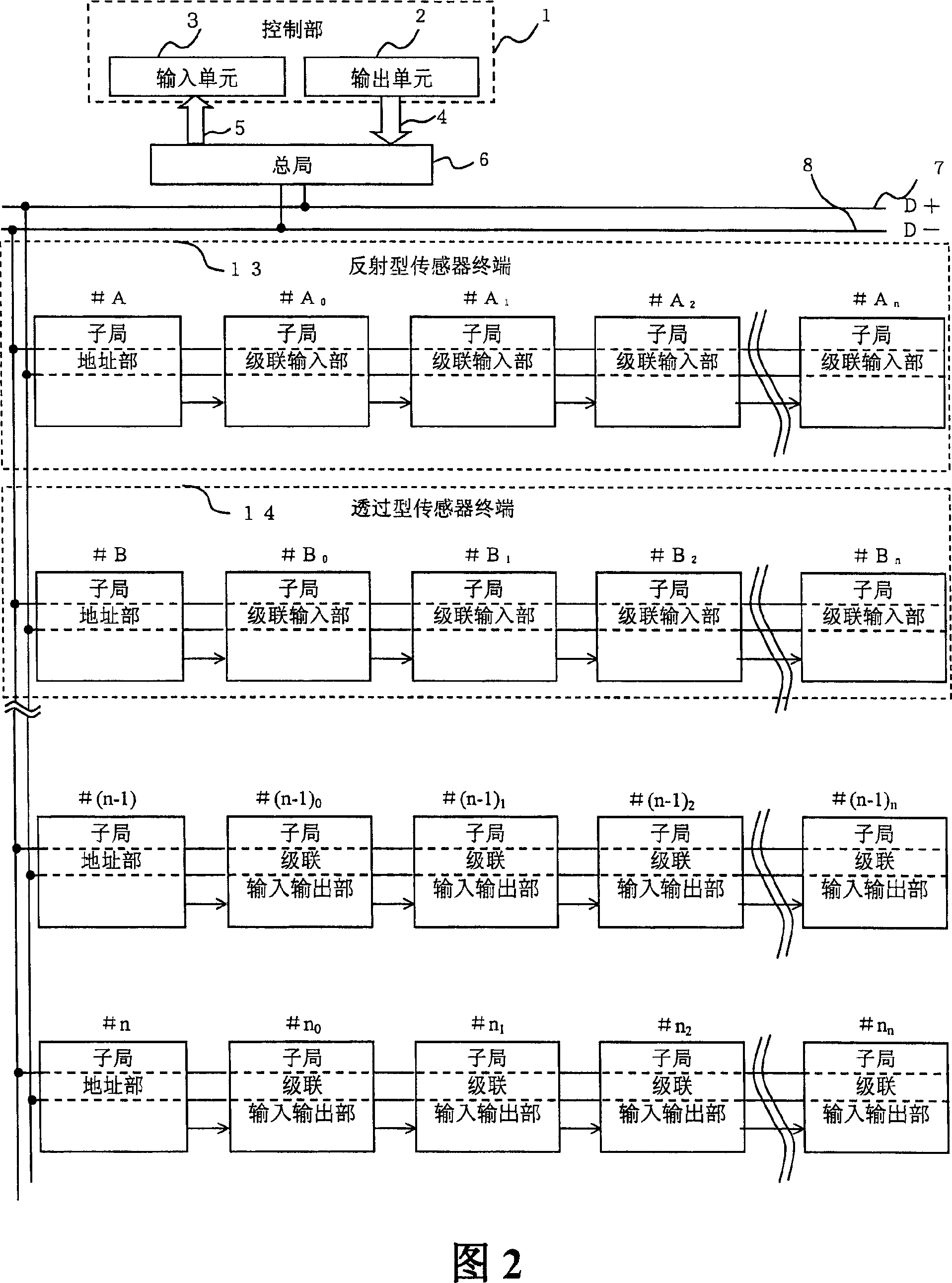
[0148]In the I / O system of FIG. 1 , the central office 6 is connected to the control unit that receives and receives input and output information, and is connected to the sub-office address unit 9 through the D+ power overlapping common data signal line 7 and the D- power overlapping common data signal line 8 . The sub-office address part 9 is connected to the sub-office input and output terminal unit 10 with the D+ power supply overlapping common data signal line 7 and the D-power supply overlapping common data signal line 8 as it is, and to a plurality of sub-offices installed on the jacket conduit 12 as sub-offices. The sub-office input-output terminal unit 10 of the office cascade input-output section transmits the cascade mobile signal 11 successively, thus forming an input-output system. ...


PUM


Abstract

The present invention relates to a terminal system which uses shared data signal line between the sub-bureau and the main bureau in the control system that conveys the monitor signal or is controlled by the control signal and the character of which is that it is provided with a plurality of cascade connected sub-bureau cascade connection input / output parts. The present invention relates to the terminal system which makes the sub-bureau cascade connected input / output parts connected with the sub-bureau address part by cascade connection respectively as the actuating starting point of each sub-bureau with cascade connection signal or timing light projecting signal by electricity or optics, namely the system which does article supervision to the shed and the assembling product line.

Description

technical field [0001] The present invention relates to a system for displaying an instruction to receive and resupply parts necessary for product assembly from items stored in a storage shed for fixed or unshaped items, and to perform an input to notify a central control unit of the receipt of the parts. A system that outputs the detection, presence, and receipt status of items in each shed. Background technique [0002] Conventionally, in an assembly line, there has been an instruction to receive a component that is a component of a product or a confirmation switch input after receipt corresponding to the instruction. In this case, the main computer sends the receiving instruction of the parts to the control device, and the control device shows the status of the instruction through the lamp and the display machine installed on the part shed where the receiving instruction is given. The operator operates the lever switch as an input of receiving completion, and the operati...

Claims


Application Information

Patent Timeline
IPC IPC(8): B65G1/137G05B19/418G05B19/048
CPCY02P90/02
Inventor 斋藤善胤锦户宪治
Owner ANYWIRE
Why Eureka
Try Eureka