Plastics composite wall brick

A technology of composite wall bricks and plastics, applied in the field of building materials, can solve the problems of limited size, inconvenient maintenance, poor recyclability of bricks, etc., and achieve the effect of high dimensional accuracy

Inactive Publication Date: 2008-01-02
冷鹭浩
View PDF0 Cites 9 Cited by
  • Summary
  • Abstract
  • Description
  • Claims
  • Application Information

AI Technical Summary

Problems solved by technology

The wall tiles of the prior art mainly include glazed pottery sintered tiles and non-fired wall tiles made of industrial waste residues, as well as marble wall tiles or granite wall tiles derived from natural stone. These wall tiles mainly exist as follows Disadvantages: First, the size is limited. On the one hand, this comes from the limitation of the processing technology. For example, it is difficult to produce large-sized bricks after sintering ceramic tiles. On the other hand, these bricks usually have a relatively heavy quality. , it is not convenient to assemble on the wall after the size is too large; second, there are many procedures in the assembly process and the labor intensity of the operators is high. For example, the brick body needs to be soaked in wate...

Method used


Image

  • Plastics composite wall brick
  • Plastics composite wall brick
  • Plastics composite wall brick

Examples


Embodiment 1

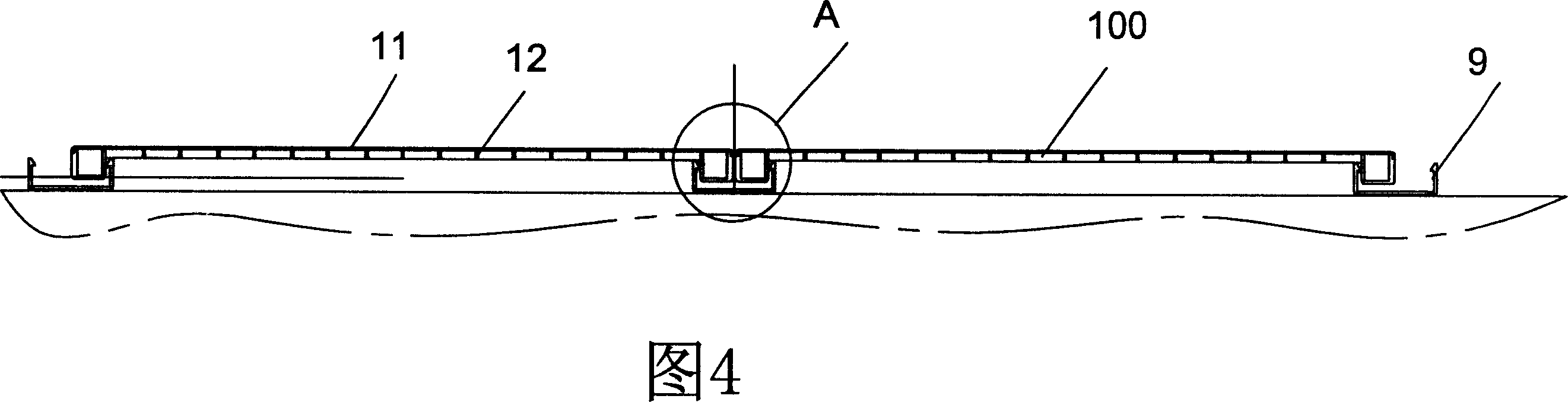
[0049] Embodiment 1, referring to Fig. 1 to Fig. 7, a plastic composite wall tile 100 of the present invention includes:

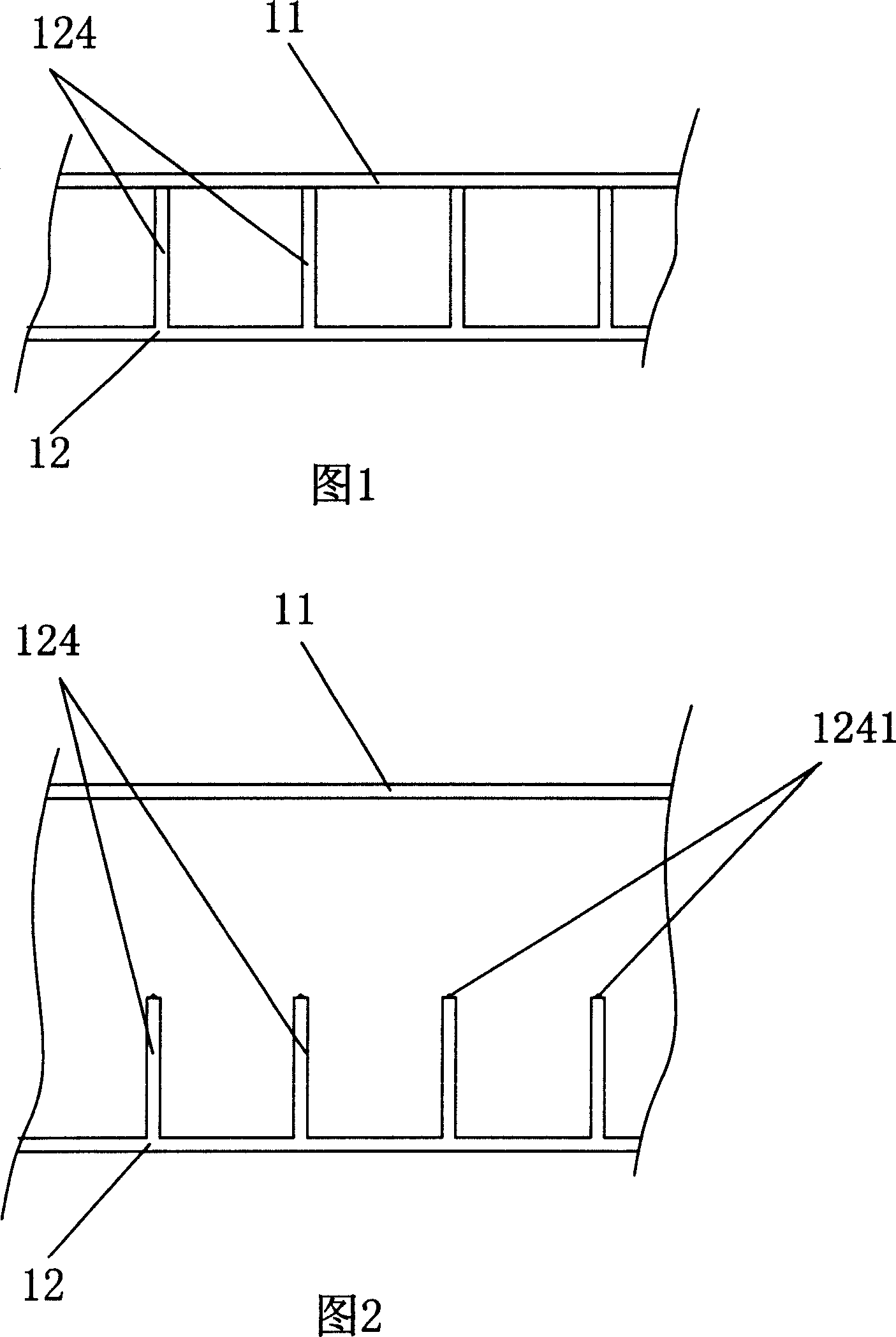
[0050] The plastic panel 11 is a monomer structure with a certain shape made by direct extrusion molding or extrusion molding, and has an upper surface and a lower surface;

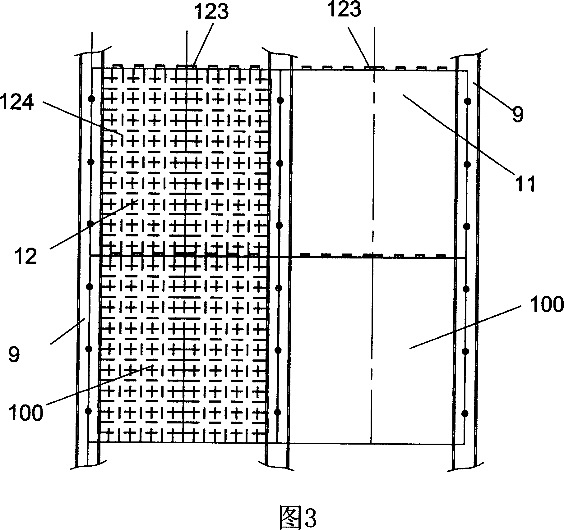
[0051] The injection molded part 12 is a single structure made by direct injection molding and matched to the shape of the plastic panel. The contact between its upper part and the lower surface of the plastic panel is connected together by welding; Fixed undercuts 121, undercuts 121 are respectively located on the left and right sides; the opposite sides are provided with positioning and water-retaining structures that can be spliced ​​with each other; The lower side is provided with a lip 122, and the upper side is provided with a groove-type stopper 123 which can realize water blocking;

[0052] The overlapping parts of the periphery of the plastic panel 11 and the corresponding p...

Embodiment 2

[0065] Embodiment 2, as shown in FIG. 16, a plastic composite wall tile 100 of the present invention is different from Embodiment 1 in that the opposite sides of the injection molded part 12 are provided with positioning and splicing. Water-retaining structure; not only includes the upper and lower sides of the plastic composite wall tile 100, that is, the lower side of the plastic composite wall tile 100 is provided with a lip 122, and the upper side is provided with a groove-type stopper 123 that can realize water-retaining; and , the left and right sides of the plastic composite wall tile 100 are also provided with such a positioning and water retaining structure, that is, a side lip 126 is provided on the convex edge 125 on the left, and a groove type stopper 127 is provided on the convex edge 125 on the right, so that , between the left and right of the plastic composite wall tile 100 is not only fixed by the buckle groove 9, but also the splicing of the side lip 126 and t...

Embodiment 3

[0066] Embodiment 3, as shown in Figure 17, a plastic composite wall tile 100 of the present invention differs from Embodiment 1 in that the groove-type block 123 is a strip-shaped continuous block, but there are multiple Open your mouth.


PUM


Abstract

The invention discloses a plastic composite brick, which is characterized by the following: comprising plastic panel and injection moulding element; squeezing and forming the plastic panel directly; or squeezing; proceeding plastic uptake form; proceeding injection made and form directly; or compositing with multiple of injecting moulding element; binding or welding the upper of the injection moulding element and the lower surface of the plastic panel together; arranging back-off or cog at the bottom of the injection moulding element; arranging orientation and water-retaining structure at the relative two edges; binding or welding the edge of the plastic panel and the coincidence edge of the injection moulding element together. This invention is environment protection, which is a new type wall covering material.

Description

technical field [0001] The invention relates to a building material, in particular to a plastic composite wall brick with a plastic injection molding composite structure. Background technique [0002] Wall brick is a commonly used decorative material for building walls, and is widely used in various large and small buildings such as family rooms, shopping malls, supermarkets, hotels and public buildings. With the substantial improvement of people's living standards, people The diversification of the pursuit of a well-off life has brought higher requirements for wall tiles. On the one hand, the wall tiles are required to be waterproof, and on the other hand, the wall tiles are required to have the effect of heat insulation, so as to meet the energy-saving design requirements of existing buildings. At the same time, the surface patterns of wall tiles are required to be varied in order to meet the different aesthetic requirements of different groups of people. The wall tiles o...

Claims


Application Information

Patent Timeline
IPC IPC(8): E04F13/18
CPCE04F13/18E04F2203/04E04F2201/0517
Inventor 冷鹭浩
Owner 冷鹭浩
Why Eureka
Try Eureka