Polarized plate structure

A polarizing plate and polarizing layer technology, which is applied in optics, optical elements, polarizing elements, etc., can solve the problems of variation in the optical properties of polarizing plates, and achieve the effects of low yellowing index, simple manufacturing process, and high Abbe number

Inactive Publication Date: 2008-01-02
OPTIMAX TECHNOLOGY CORPORATION
View PDF8 Cites 10 Cited by
  • Summary
  • Abstract
  • Description
  • Claims
  • Application Information

AI Technical Summary

Problems solved by technology

[0007] Another object of the present invention is to provide a polarizer structure that has moderate water absorption

Method used


Image

  • Polarized plate structure
  • Polarized plate structure
  • Polarized plate structure

Examples


Embodiment Construction

[0022] Here, the present invention will describe some embodiments in detail. It is to be noted, however, that the invention may be practiced in a wide range of other embodiments than those explicitly described, and that the scope of the invention is not limited to the above-described embodiments, as determined by the claims.

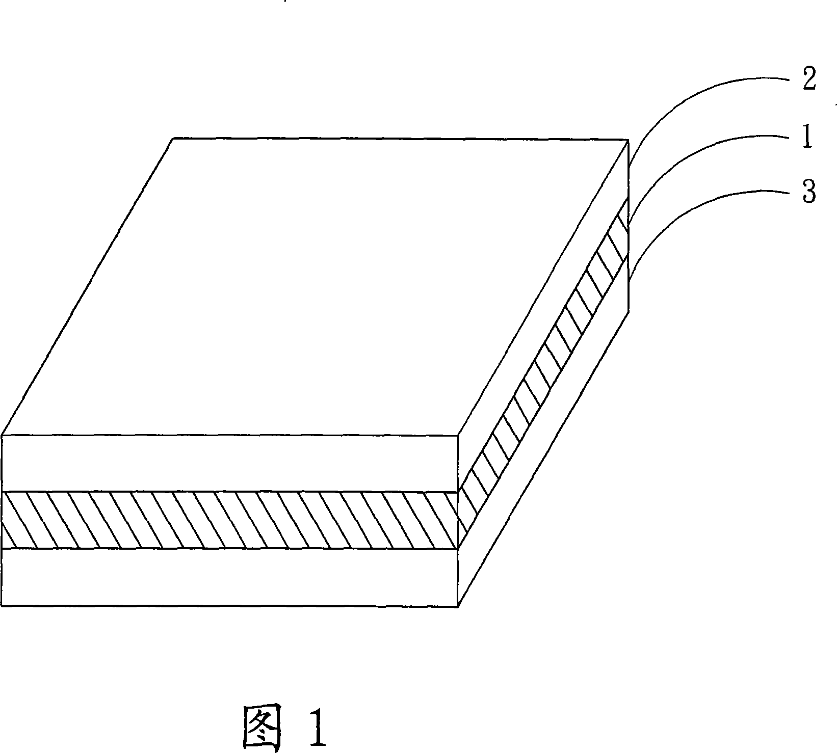
[0023] FIG. 1 is a perspective view of a specific embodiment of a polarizer structure of the present invention. Shown with reference to Fig. 1, the polarizer structure of the present invention is that the upper surface and the lower surface of polarizing layer 1 have first optical film 2 and second optical film 3 respectively, and described first optical film 2 and second optical film 3 Among them, at least one optical film is a polymethyl methacrylate (Polymethyl Methacrylate, PMMA) optical film.

[0024] In addition, in the above-mentioned first optical film 2 and second optical film 3, one optical film is a polymethyl methacrylate optical film, and t...


PUM


Abstract

The present invention relates to a polarized light board structure which is provided with a polarized light layer, a first optical film and a second optical film, the first optical film is formed above the polarized light layer and the second optical film is formed below the polarized light layer, wherein, at least one optical film selected from the first optical film and the second optical film is polymethyl methacrylate optical film. Into the bargain, the optical film is formed by pasting the mixed solution to the polarized light board and doing heat treatment when penetrating the mixed solution and distributing on the substrate to prepare for making have finished, or the optical film is formed by penetrating the mixed solution and distributing on the substrate and doing thermal treatment.

Description

technical field [0001] The invention relates to a polarizing plate structure, in particular to a polarizing plate structure which is a polymethyl methacrylate optical film prepared by a solvent casting film technique. Background technique [0002] The traditional polarizer structure is composed of optical films on the upper and lower surfaces of the polarizing substrate, and the base materials of such optical films are generally triacetate (TAC: triacetate), PC (polycarbonate), and COP. The typical TAC film can be further used as a protective and supporting film for the optical film. Therefore, in addition to the required optical properties, the general TAC film must also have a certain strength and have high temperature resistance and moisture resistance to achieve optical properties. The use requirements of the film or the effect of providing protection for the optical film formed by the TAC film (refer to the following patents: JP4342202, TW499573, JP2000-324055, JP2001-2...

Claims


Application Information

Patent Timeline
IPC IPC(8): G02B5/30G02B1/04G02B1/10
Inventor 李光荣曾盈达王丹青林宜贞庄毓蕙
Owner OPTIMAX TECHNOLOGY CORPORATION
Why Eureka
Try Eureka