Optical element

A technology of optical components and components, applied in the field of optical components, can solve problems such as difficult manufacturing, and achieve the effect of uniform electric field and uniform conversion

Inactive Publication Date: 2008-01-02
KONINKLIJKE PHILIPS ELECTRONICS NV
View PDF2 Cites 4 Cited by
  • Summary
  • Abstract
  • Description
  • Claims
  • Application Information

AI Technical Summary

Problems solved by technology

These Fresnel lenses have small, deep grooves that are difficult, if not impossible, to manufacture even with diamond turning
Also, Fresnel lenses are designed only for specific wavelengths

Method used


Image

  • Optical element
  • Optical element
  • Optical element

Examples


Embodiment Construction

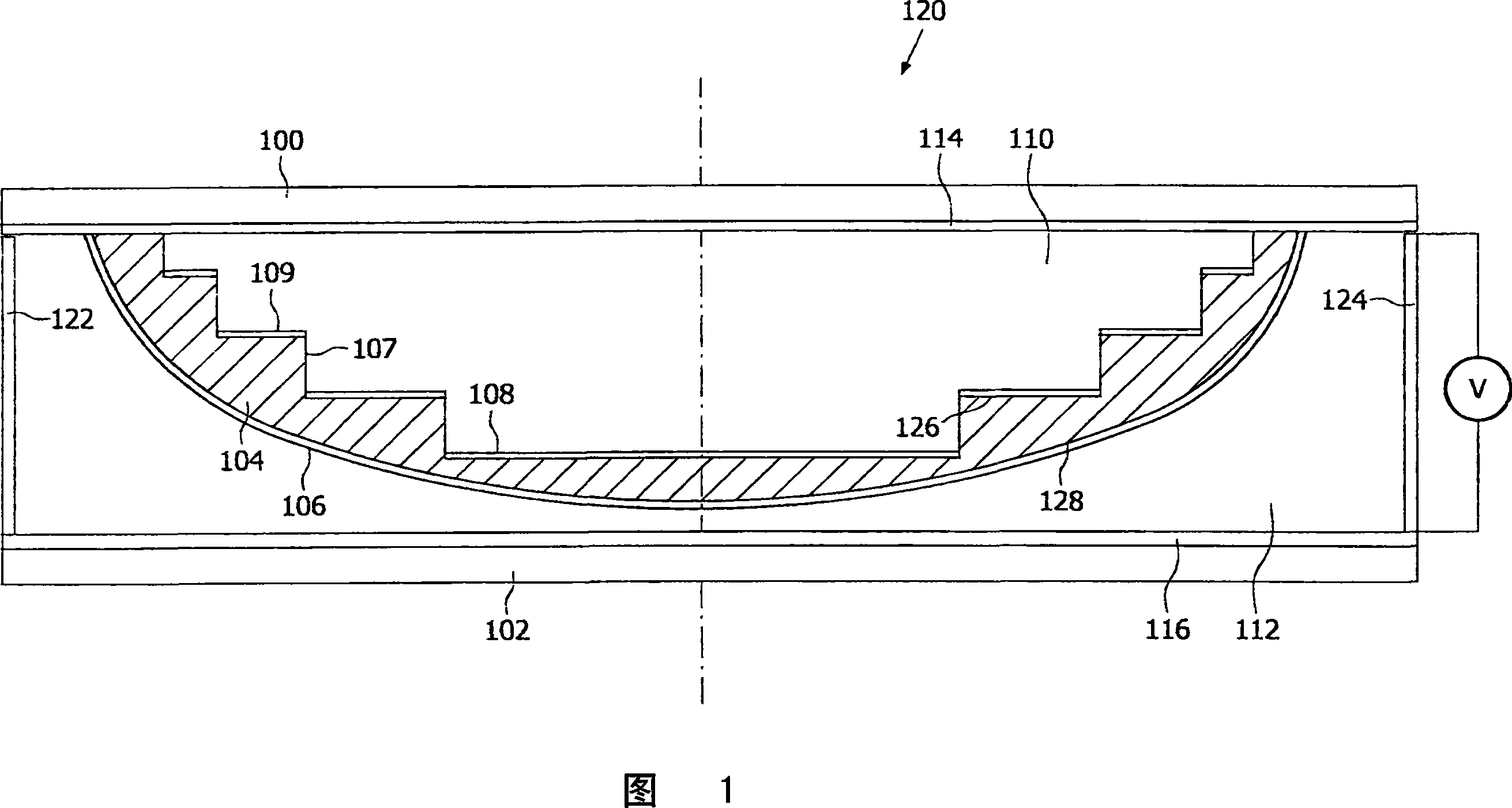
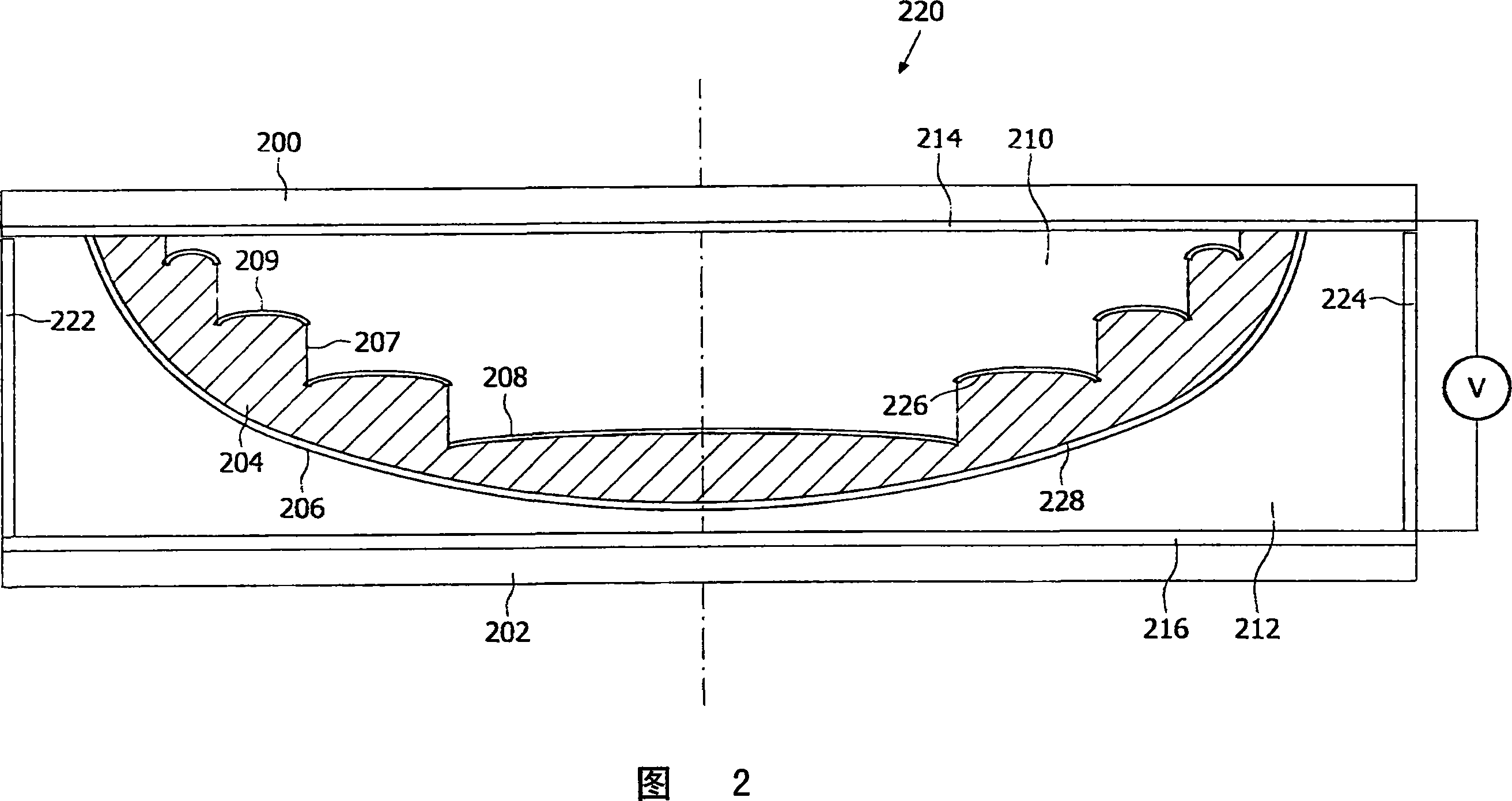
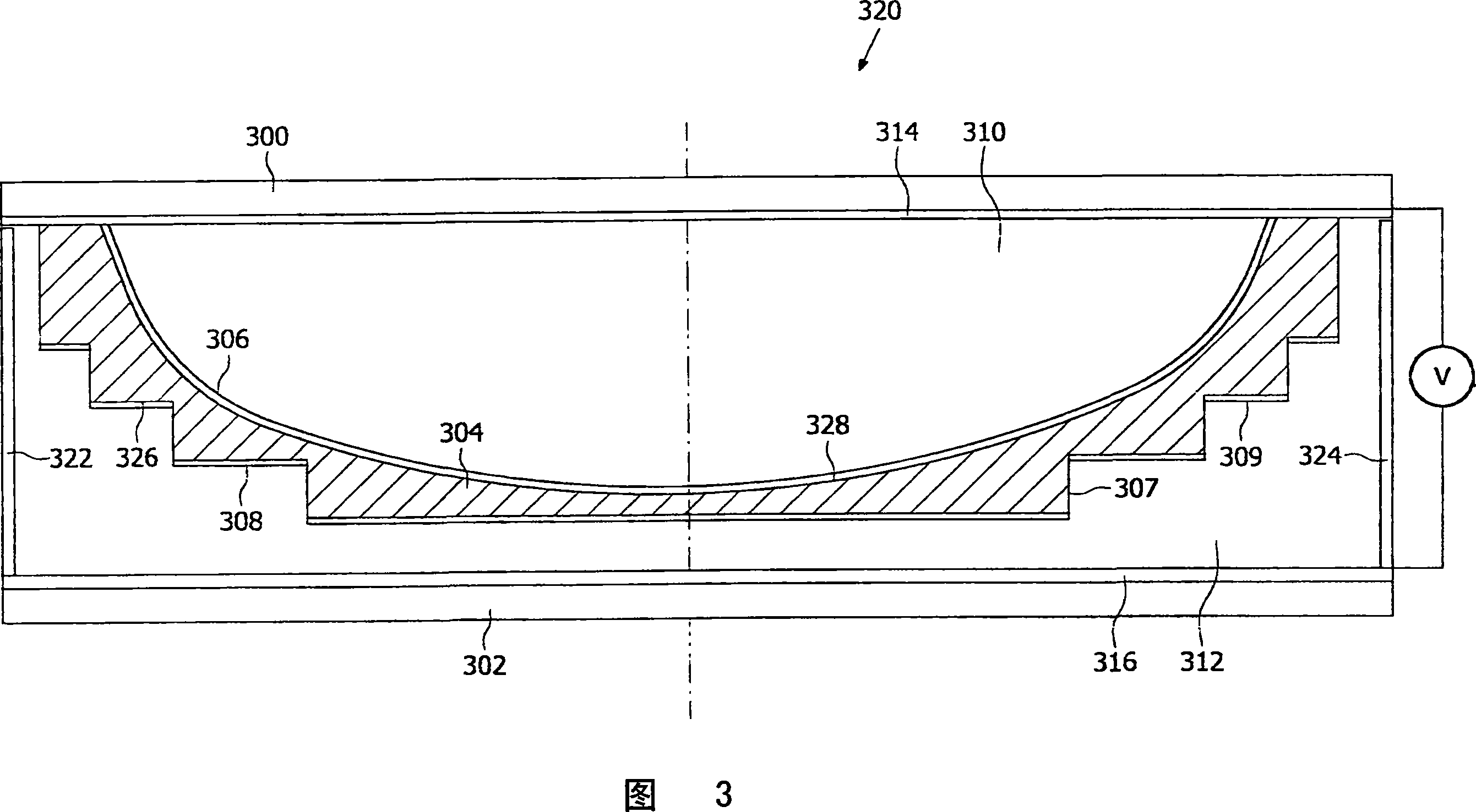
[0018] Fig. 1 is an enlarged cross-sectional view of one embodiment of an optical element according to the present invention. In this embodiment, the optical element 120 includes two transparent plates 100, 102, and two transparent electrodes 114, 116, which are respectively arranged perpendicular to the optical axis indicated by the dashed line. The electrodes are connected to a power supply V and are joined by insulating spacers 122 , 124 . The two electrodes may be formed, for example, of indium tin oxide (ITO) coated glass and are typically applied by evaporation or sputtering on the inner sides of the transparent plates 100, 102. The optical element also comprises a fluid material 104 having a variable refractive index depending on the voltage applied between the electrodes, preferably an AC voltage. In this embodiment, the element is a liquid crystal (LC) lens and the fluid material is a liquid crystal material. The thin layer of material 104 is sandwiched between a fi...


PUM


Abstract

An optical element (120; 220; 320; 420) includes a fluid material (104; 204; 304; 404) which is held between a first surface (106; 206; 306; 406) and a second surface (108; 208; 308; 408) and has a refractive index which is variable in response to variation of an applied field. The first surface and said second surface have respective first and second cross-sectional profiles, which vary in height when measured parallel to the optical axis of the optical element, across the respective first and second surfaces.

Description

technical field [0001] The present invention relates to an optical element, in particular to an optical element comprising a fluid material with a variable refractive index, especially but not limited to a liquid crystal material. Background technique [0002] Optical focusing systems with variable focal lengths are widely used in optical systems. In order to avoid the use of mechanical units to change the focal length, variable focal length non-mechanical optical elements, such as liquid crystal (LC) lenses, have been proposed. [0003] US Patent 4,466,703 describes a variable focus lens with a liquid crystal (LC) sandwiched between two electrodes, one of which consists of a plurality of concentric ring electrodes. The power supply applies different potentials to each ring-shaped transparent electrode and applies an electric field with oblique intensity distribution to the liquid crystal, thereby causing the liquid crystal to produce a refractive index distribution with a ...

Claims


Application Information

Patent Timeline
Patent Type & Authority Applications(China)
IPC IPC(8): G02F1/29G02B3/14G02B26/02
CPCG02F1/29G02B26/005G02B3/14G02F2001/294G02F1/294
Inventor E·J·K·弗斯特根
Owner KONINKLIJKE PHILIPS ELECTRONICS NV
Why Eureka
Try Eureka