Canal evaporator

An evaporator and steam technology, applied in the direction of evaporator/condenser, heat exchanger type, indirect heat exchanger, etc., can solve the problems of weakening the effect of surface strengthening measures, drying up inside the tube, and small proportion, so as to reduce energy consumption The effect of conversion and utilization efficiency, enhanced heat transfer, and simple processing

Inactive Publication Date: 2008-01-09
TSINGHUA UNIV
View PDF0 Cites 19 Cited by
  • Summary
  • Abstract
  • Description
  • Claims
  • Application Information

AI Technical Summary

Problems solved by technology

At the same time, this single tube-side evaporation and boiling process will inevitably lead to complex gas-liquid two-phase flow
When there is a two-phase flow in the tube, the gas-liquid will be in the flow pattern of bubble, gas plug, ring or stratified flow according to the dryness, which will greatly increase the flow resistance and operation instability, and control the operation of the system, etc. have a very negative impact on
Although the annular flow and the thin liquid film evaporation flow pattern have good he

Method used


Image

  • Canal evaporator
  • Canal evaporator
  • Canal evaporator

Examples


Example Embodiment

[0025] The present invention will be further explained below in conjunction with the drawings.

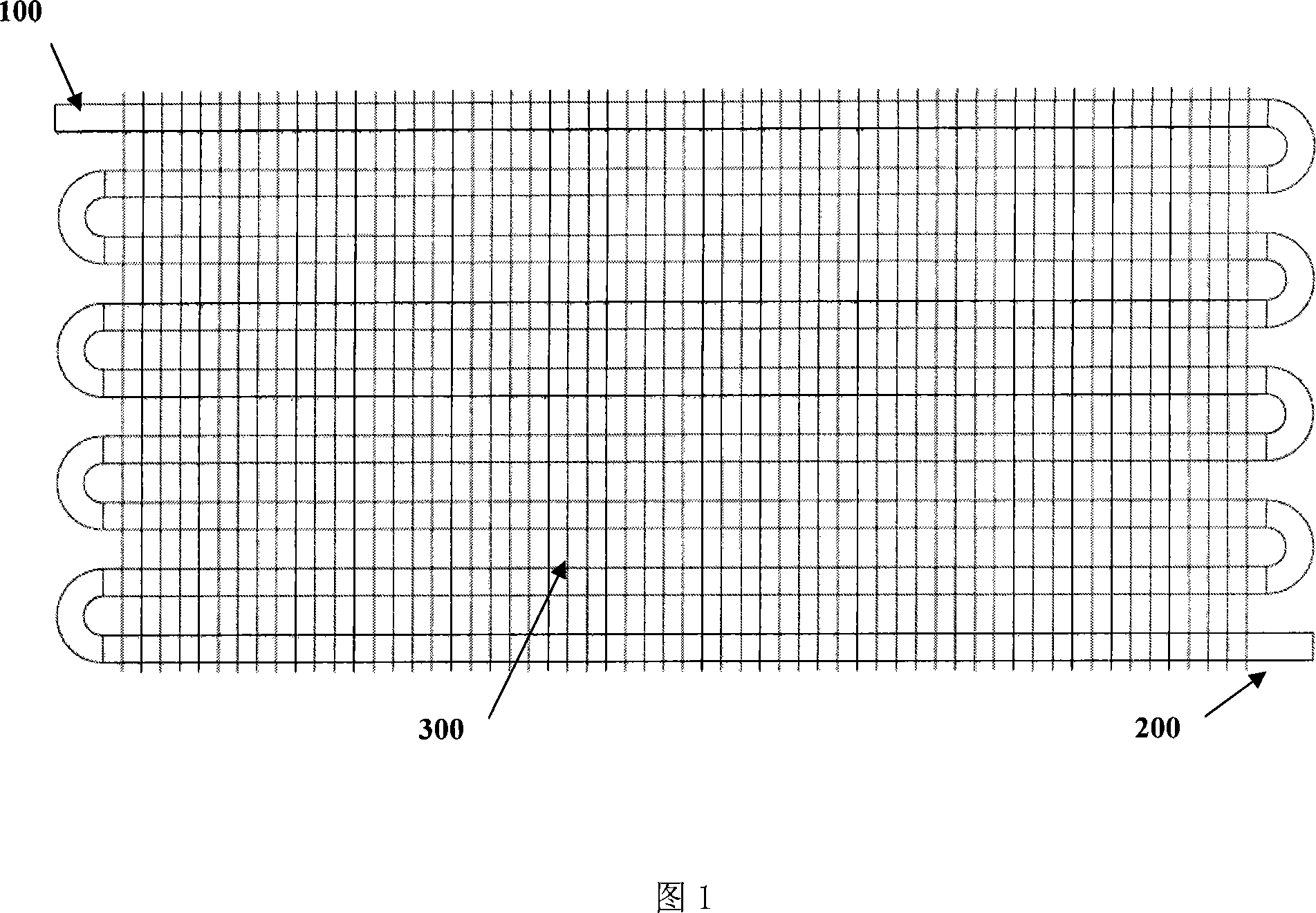
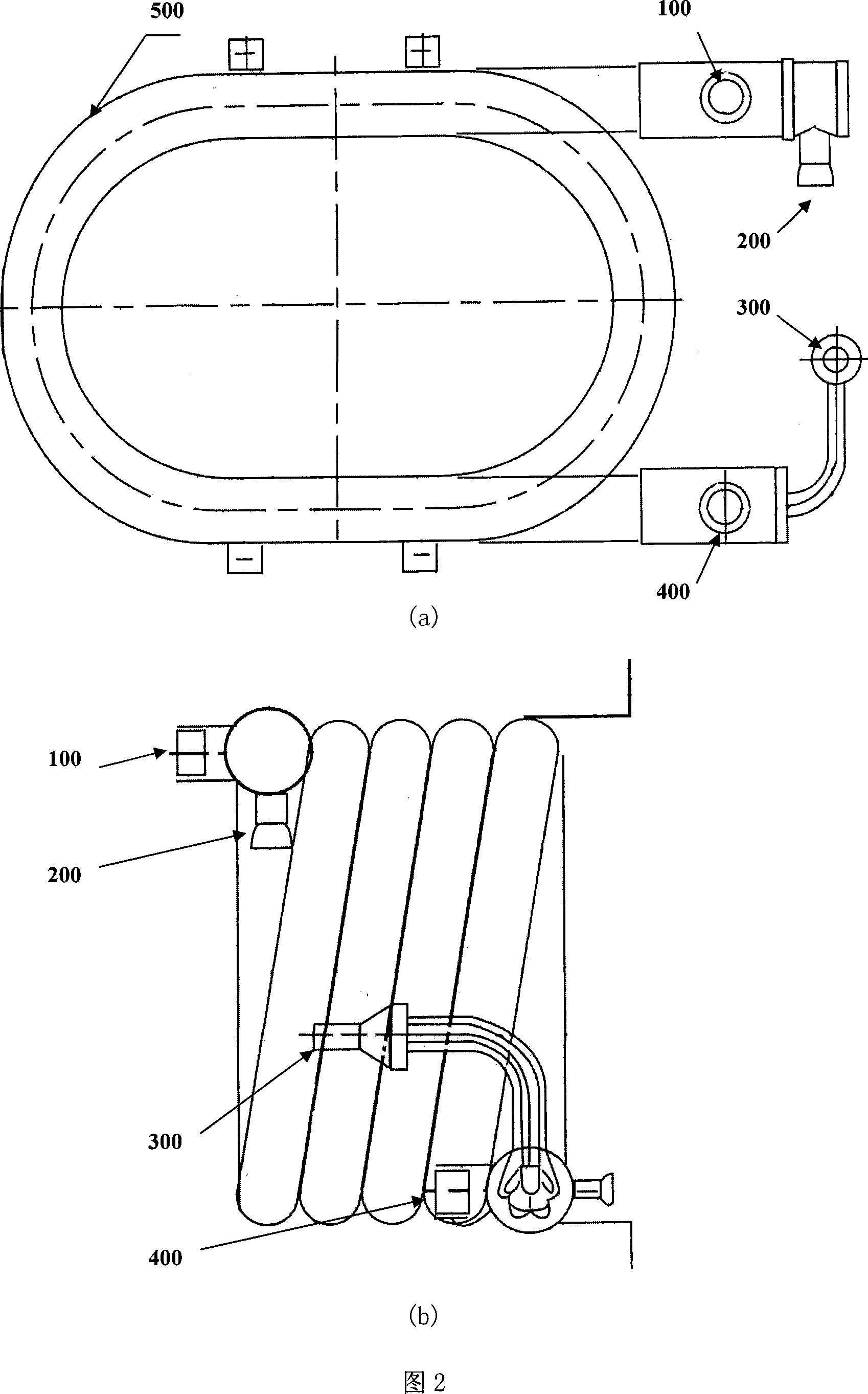
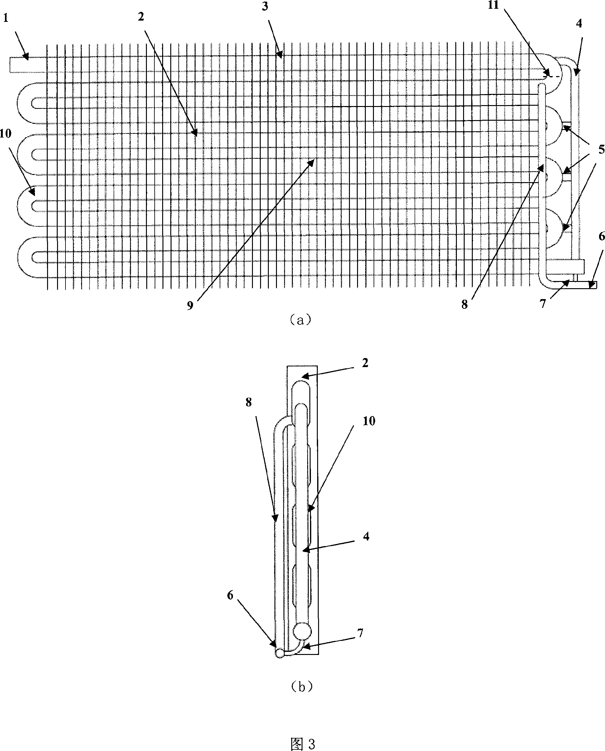
[0026] Fig. 3 is a schematic diagram of a novel high-efficiency air heating (or cooling air) evaporator of the present invention. Including 1. Vapor outlet of vaporized liquid (or refrigerant, the same below.), 2. Fins, 3. Overheating section, 4. Gas collecting exhaust pipe, 5. Gas collecting exhaust port, 6. Vaporized liquid inlet 7. The liquid phase circulation return pipe of the remaining evaporated liquid, 8. The inlet pipe of the evaporated liquid, 9. The serpentine heat exchange section, 10. The serpentine heat exchange pipe, 11. The separator. A new type of high-efficiency air-heated evaporator. The heat exchange part of the integral serpentine heat exchange tube (10) is divided into a serpentine heat exchange section (9) and a superheating section (3) by a separator (11). The uppermost part is the vaporized liquid vapor. Exit (1), the other end is sealed. The serpentine heat ex...


PUM


Abstract

The invention relates to a tube evaporator, belongs to the thermal equipment technical area. The air heating tube evaporator includes the evaporator export of the liquid vapor (1), fin (2), overheating segment (3), gas collection and exhaust port (5), the evaporator import of liquid (6), snake heat exchange segment( 9), snake heat tube (10), divider (11). The one end of the snake heat tube (10) is sealed by another end of the evaporator export of liquid vapor (1), it is divided into overheating segment (3) and the snake heat exchange segment (9) by the divider (11), and in the tube has the porous layer; the top pf the exhaust-gas tube and the gas collection tube (4) in the snake tube connect the top of the divider (11) which is located in the overheating segment (3). The remaining liquid of the evaporation returns to the evaporator import of liquid (6) and cycles evaporation; the invention also provides a fluid heat-pipe evaporator. The invention has high- heat exchange performance, is conducive to maintain the efficient evaporation process; simple processing, enhanced the work efficiency and the adapt ability of the evaporator.

Description

technical field [0001] The invention relates to a novel high-efficiency in-pipe evaporator, which belongs to the technical field of thermal equipment. Background technique [0002] In-pipe evaporator is a kind of thermal equipment, which is widely used in power, chemical industry, air-conditioning engineering and refrigeration engineering, such as refrigerators, freezers, air-conditioning systems, chemical and petrochemical process evaporators, etc. There are two main forms, one is liquid heating type, such as the common casing evaporator; the other is air heating type, such as household air conditioners, large refrigeration devices, etc. [0003] Figure 1 is a household split air conditioner evaporator, which consists of evaporation tubes and fins outside the tubes. Among them, 100-evaporated liquid (refrigerant for the air-conditioning refrigeration system) vapor outlet, 200-evaporated liquid (refrigerant for the air-conditioning refrigeration system) inlet, 300-pipe oute...

Claims


Application Information

Patent Timeline
IPC IPC(8): F28D1/047F25B39/02
Inventor 彭晓峰吴迪陆规张扬王珍
Owner TSINGHUA UNIV
Why Eureka
Try Eureka