Full hydraulic rock core drilling machine unit head

A technology of core drilling rig and power head, which is applied in the direction of rotary drilling rig, drilling equipment, earthwork drilling and production, etc. It can solve the problems of not being able to work continuously for a long time, the skeleton oil seal is easy to wear, and the drilling rig cannot work, so as to reduce pitting corrosion , Good heat dissipation effect, prevent backflow and splashing effect

Inactive Publication Date: 2008-01-16
H H DRILL TECH DRILLING MACHINERY CO LTD
View PDF0 Cites 12 Cited by
  • Summary
  • Abstract
  • Description
  • Claims
  • Application Information

AI Technical Summary

Problems solved by technology

The temperature of the lower bearing and frame oil seal will rise sharply when the spindle speed increases. The bearing and frame oil seal are wrapped in lubricating oil, and the heat dissipation depends on oil conduction. The heat dissipation speed is slow. time continuous work
In addition, the drilling rig sometimes needs the main shaft to deflect 45°~90° to carry out the drilling work of the inclined hole with continuously adjustable angle. When the inclined hole is drilled, the lower end bearing and the skeleton oil seal are subjected to comprehensive bending and torsional loads, and the eccentric wear is serious, and the skeleton oil seal is easy to wear and tear. After that, it is easy to leak oil. For reliable sealing, the manufacturing precision and hardness of the main shaft, bushing and other related parts should be high. Increased manufacturing costs, such as too tight fit, a sharp rise in oil temperature, the rig can not work
In addition, the oil level of the lubricating oil in the box is low and the heat dissipation is fast, but the gear lubrication is poor. When the oil level is high, the lubrication effect is good, but the oil churning increases significantly, and the oil churning generates heat, causing power loss and poor heat dissipation.

Method used


Image

  • Full hydraulic rock core drilling machine unit head
  • Full hydraulic rock core drilling machine unit head
  • Full hydraulic rock core drilling machine unit head

Examples


Embodiment Construction

[0014] A fully hydraulic core drilling rig power head, driven by dual hydraulic motors, parallel power input, two-stage gear transmission, hydraulic stepless speed regulation, hydraulic chuck clamping and long stroke feed mode.

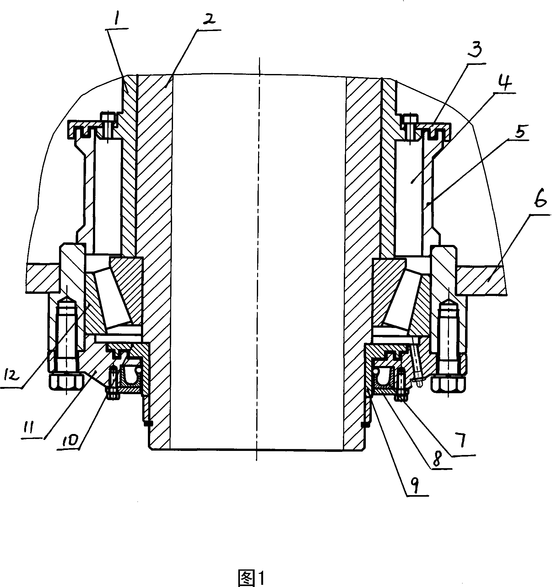
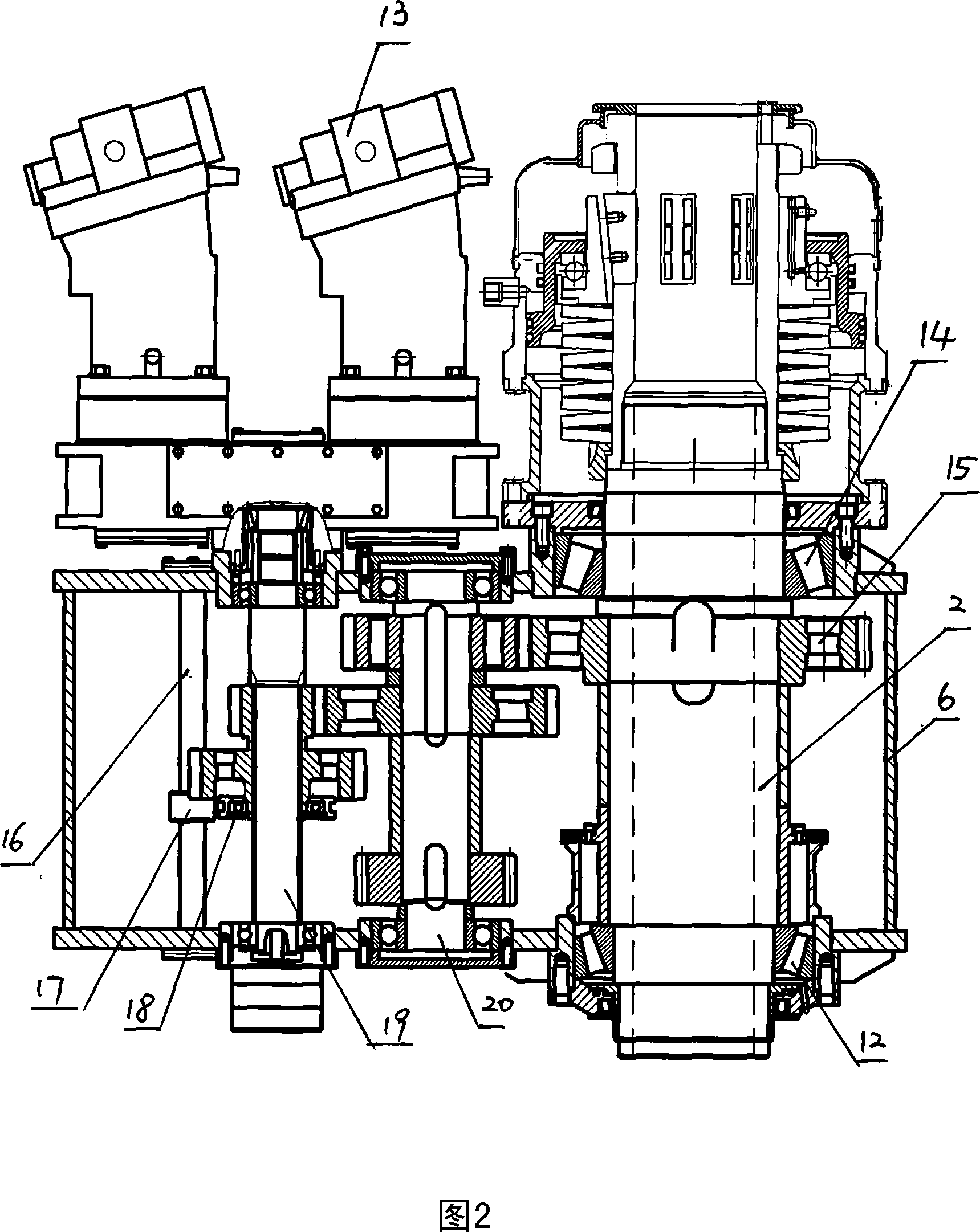
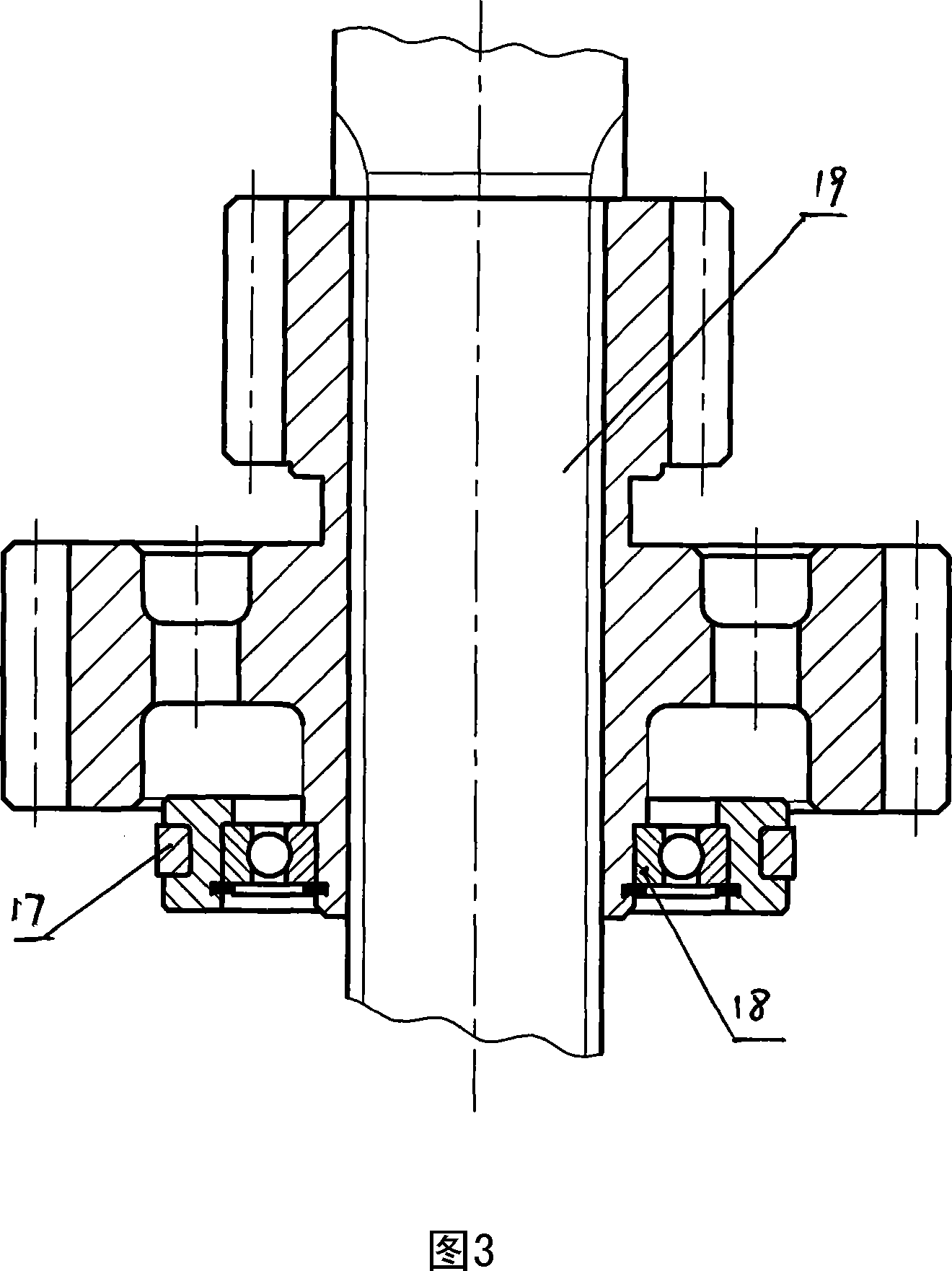
[0015] It is equipped with a power head box 6, the main shaft 2 is vertically arranged at the front of the box body 6, and double hydraulic motors 13 are used for parallel power input. A variable speed transmission mechanism is provided between the motor 13 and the main shaft 2. The transmission transmission mechanism is provided with a transmission shaft 19 and an intermediate shaft 20 arranged vertically side by side. The hydraulic motor 13 is connected to the upper end of the transmission shaft 19. A pair of constant meshing gears are used to drive between them. The transmission shaft 19 is equipped with a two-stage speed change dual gear, and the intermediate shaft 20 is equipped with a fixed gear that cooperates with the transmission shaft dual ge...


PUM


Abstract

A power head for all-hydraulic operated drill is driven by double hydraulic motor and adopts the mode of power input, double-geared drive, hydraulic stepless speed regulation, hydraulic chuck clamping and long-travel feeding. A middle and lower labyrinth seals and a skeleton oil seal form a three-layer sealing device of a main shaft of the drill power head. The drill is lubricated by using mixed lubricating grease and thin oil. The middle part realizes labyrinth sealing by matching a supporting sleeve and a rotary plate, so as to provide a lower end bearing sufficient accumulated grease and heat dissipation space, guarantee the reliable lubrication and heat dissipation of the bearing, and increase secondary oil splashing and splash lubrication effect. The lower part realizes labyrinth sealing by matching an oil removal driving disk and an end cover, so as to effectively preserve and retain lubricating grease in the lower bearing box. The main shaft operates at high speed to cause temperature rising, and when the lubricating grease is diluted, its loss can be effectively prevented. The lower skeleton is oil sealed to prevent backflow and splashing of the drilling fluid, and further prevent the outer discharge of the lubricating grease when being diluted to take secondary protection effect.

Description

technical field [0001] The invention relates to a surface core drilling rig, in particular to a fully hydraulic power head for the core drilling rig. technical background [0002] The power head of the full hydraulic drilling rig in the prior art uses a hydraulic motor to drive the main shaft to perform drilling. The lower bearing of the main shaft and the gear in the box are all lubricated with thin oil, and the lower end of the main shaft is only designed with a skeleton oil seal. The temperature of the lower bearing and frame oil seal will rise sharply when the spindle speed increases. The bearing and frame oil seal are wrapped in lubricating oil, and the heat dissipation depends on oil conduction. The heat dissipation speed is slow. Time works continuously. In addition, the drilling rig sometimes needs the main shaft to deflect 45°~90° to carry out the drilling work of the inclined hole with continuously adjustable angle. When the inclined hole is drilled, the lower end...

Claims


Application Information

Patent Timeline
Patent Type & Authority Applications(China)
IPC IPC(8): E21B3/02
Inventor 文治国马松岭杨东明
Owner H H DRILL TECH DRILLING MACHINERY CO LTD
Why Eureka
Try Eureka