Modified grinder cupula magnetizing and demagnetization controller

A grinding machine sucker, charging and demagnetization technology, applied in the direction of magnetic objects, electrical components, circuits, etc., can solve the problems of high output power of the main circuit H bridge, inability to demagnetize the workpiece, and adhesion, so as to enhance anti-interference and reliability, improve Effect of demagnetization accuracy and shortening demagnetization time

Inactive Publication Date: 2008-01-16
西安鸣士机电开发有限公司
View PDF1 Cites 3 Cited by
  • Summary
  • Abstract
  • Description
  • Claims
  • Application Information

AI Technical Summary

Problems solved by technology

[0003] However, there are still many deficiencies in these current charging and demagnetizing devices: ①Frequent switching of relay contacts will cause electric corrosion due to arcing, affecting conduction or adhesion, thus making the product invalid
②Simple forward and reverse switching can not demagnetize the workpiece very well, and the demagnetization effect is very poor; ③Although the demagnetization effect of "Grinder Electromagnetic Chuck Charging and Demagnetization Controller" is good, the output power of the main circuit H bridge is relatively large, and the device is easy to work for a long time. The device is damaged due to heat generation, and the failure rate is high
④ There are two relays connected to the opposite corner of the main circuit H bridge, and the voltage cannot be adjusted during magnetization.

Method used


Image

  • Modified grinder cupula magnetizing and demagnetization controller
  • Modified grinder cupula magnetizing and demagnetization controller
  • Modified grinder cupula magnetizing and demagnetization controller

Examples


Embodiment Construction

[0015] Accompanying drawing is embodiment of the present invention.

[0016] The content of the present invention will be further described below in conjunction with accompanying drawing:

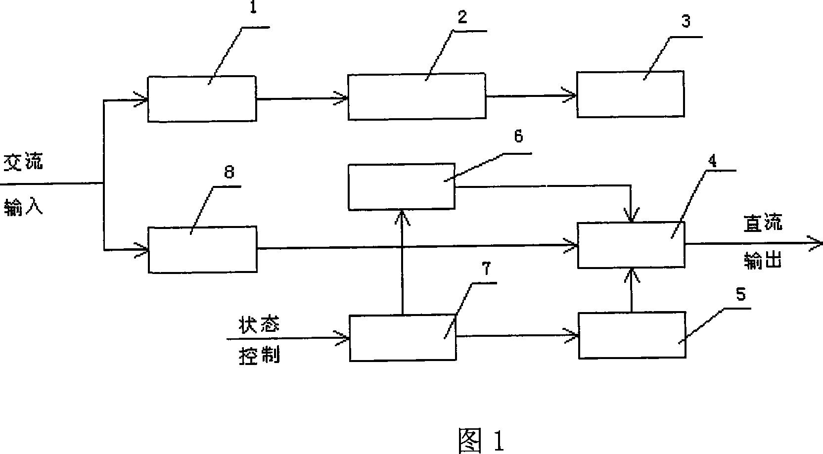
[0017] Referring to Figure 1, it consists of a main loop and a control loop. The main loop includes an H-bridge inverter circuit. The control loop includes output voltage forward and reverse switching control and output voltage amplitude control. The AC power supply is divided into two circuits and connected to transformer 1 and On the rectifier 8, the transformer 1 is connected with the rectification and voltage stabilization circuit 2, the rectification and voltage stabilization circuit 2 is connected with the control loop circuit 3, the rectifier 8 is connected with the H-bridge inverter 4, the state control 9 is connected with the single-chip microcomputer 7, and the single-chip microcomputer 7 is in turn The two circuits are respectively connected to the filter circuit 6 and the trigge...


PUM


Abstract

The invention provides an improved grinder sucker magnetizing and demagnetizing controller, which consists of a main circuit and a control circuit. The main circuit includes an H-bridge inverting circuit, and the control circuit includes positive and negative switch control and amplitude control of output voltage. The upper tube at one side of the H-bridge inverting circuit is connected with a relay at the two ends respectively, which is in parallel connection with a power tube and in connection with a filtering circuit. In magnetizing, the invention transmits adjustable DC voltage through relay and power tube, and in demagnetizing, the invention transmits adjustable voltage after alternative connection, and is connected with electromagnetic sucker directly; the control circuit consists of a SCM, a photoelectric coupler, and a timer, which are connected with each other. The control circuit makes positive and negative switch on output voltage and transmits the voltage amplitude. By making magnetizing voltage adjustable, the invention enhances the magnetizing precision, lowers magnetizing power consumption, and reinforces the performances of anti-disturbance and liability. The H-bridge transmits adjustable and excellent demagnetizing effect; after tests, all performance indexes are proved to be superior to those of prior arts. Furthermore, the invention has the advantages of high reliability, good anti-disturbance, simple structure, and convenient installation.

Description

technical field [0001] The invention relates to a charge and demagnetization controller, in particular to an improved charge and demagnetization controller for an electromagnetic chuck of a grinding machine. Background technique [0002] Surface grinders usually use electromagnetic chucks to clamp workpieces. In order to reliably attract and remove workpieces conveniently, the design of the charge and demagnetization control circuit of the electromagnetic chuck is very important. The more advanced charge and demagnetization controller currently used in our country controls the magnitude of the voltage by controlling the trigger conduction of the thyristor, and completes the direction switching of the voltage by controlling the internal and external relays (or contactors), or through The main circuit consists of four power tubes connected in a bridge type to form an H-bridge inverter to output DC voltage with adjustable amplitude and direction for non-contact output, directly...

Claims


Application Information

Patent Timeline
IPC IPC(8): H01F13/00
Inventor 蒋高峰王云富
Owner 西安鸣士机电开发有限公司
Why Eureka
Try Eureka