

Fluorophor paste and method for manufacturing display device
A technology for phosphors and pastes, applied in the field of phosphor pastes, can solve the problems of difficult dispersing agents, increase the addition amount, and large molecular weight, and achieve the effects of increasing affinity and reducing brightness deterioration.
- Summary
- Abstract
- Description
- Claims
- Application Information
AI Technical Summary
Problems solved by technology
Method used
Image

Examples
Embodiment 1~19
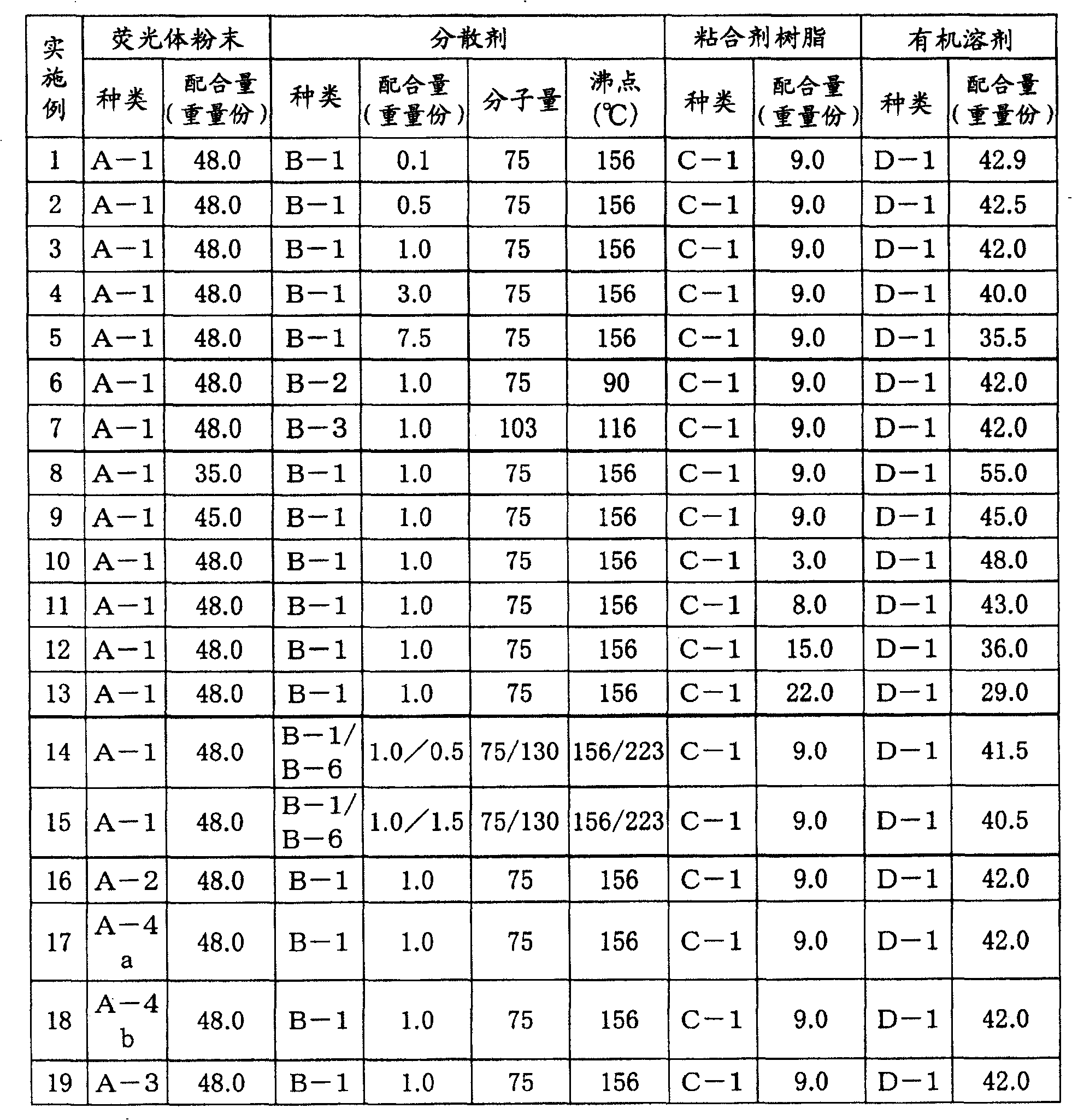
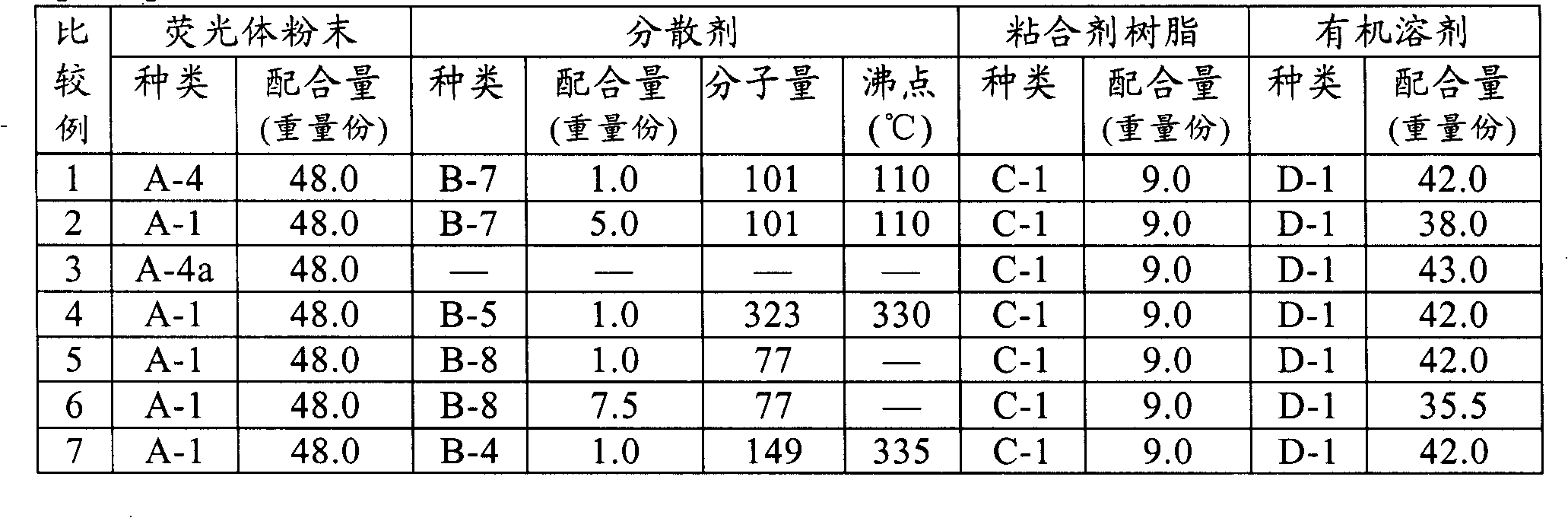
[0072] Phosphor paste was formulated using the following materials.
[0073] (A) Phosphor powder
[0074] ・(A-1) Cyan phosphor powder: BaMgAl 10 o 17 : Eu (hereinafter referred to as BAM), the average particle size is 2.4μm
[0075] ·(A-2) Red phosphor powder: (Y, Gd)BO 3 : Eu (hereinafter referred to as YGB), the average particle size is 2.3μm
[0076] ・(A-3) Green phosphor powder: Zn 2 SiO 4 : Mn (hereinafter referred to as ZSM), the average particle size is 2.5μm
[0077] ・(A-4a) ZSM coated with a zinc oxide layer with an average thickness of 0.2 μm
[0078] ・(A-4b) ZSM coated with an yttrium oxide layer with an average thickness of 0.2 μm
[0079] It should be noted that, as a method of coating the surface of the phosphor with a metal oxide in (A-4a) and (A-4b), the chloride, nitrate, etc. of the metal oxide (zinc oxide or yttrium oxide) to be coated It is formed by adding ZSM powder into the aqueous solution, fully stirring and drying, and then firing at 400°C to...
Embodiment 1
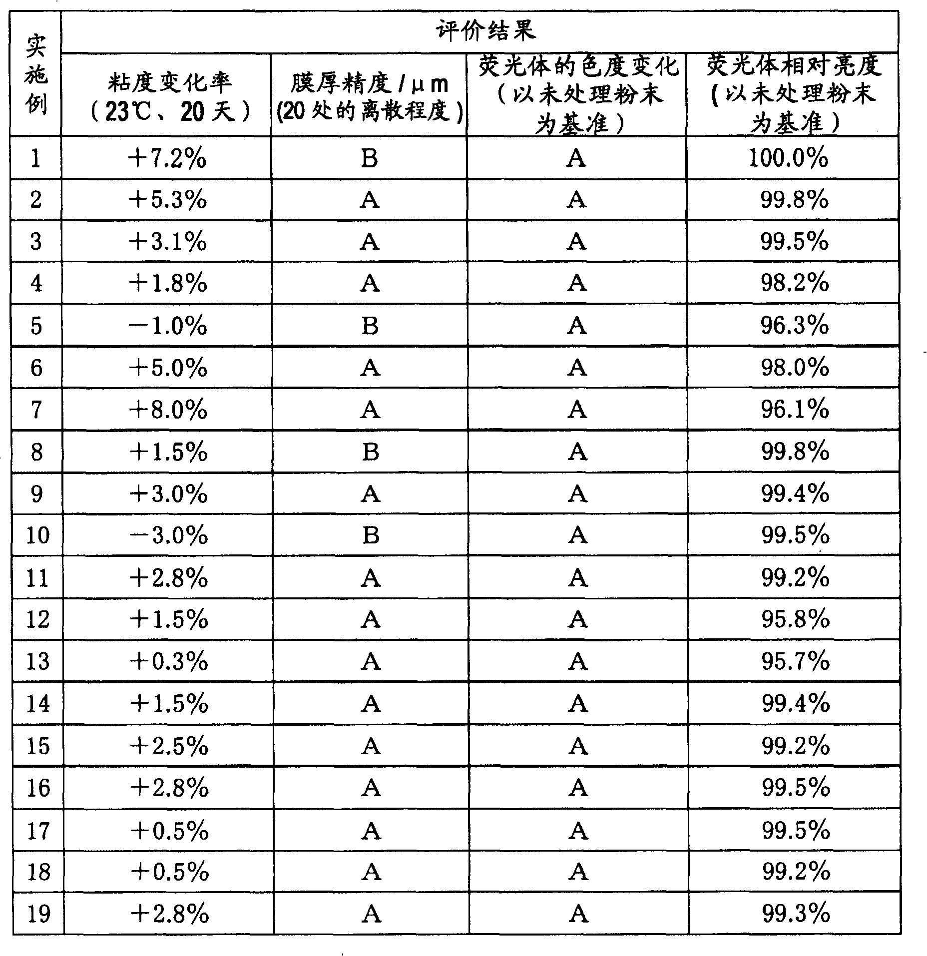
[0162] Among Examples 1 to 5, in Example 3 in which the compounding amount of the dispersant was 1.0 parts by weight and in Example 4 in which the compounding amount of the dispersant was 3.0 parts by weight, the change in viscosity was small and the coatability was also good. In Example 5, the relative brightness of the phosphor is reduced to a certain extent due to the large amount of addition. In Examples 6 and 7 where the compounding amount of the dispersant was 1.0 parts by weight and the type of the dispersant was changed, Example 6 obtained a result not much different from that of Example 1, and Example 7 used a dispersant with a large molecular weight, so the viscosity The rate of change increases and the relative brightness of the phosphor decreases.
[0163] Examples 8 to 13 are phosphor slurries with the same type of components but different compounding amounts of phosphor powders. Among them, the slurries of the compounding ratios of Examples 9 and 13 do not cause ...
PUM
| Property | Measurement | Unit |
|---|---|---|
| boiling point | aaaaa | aaaaa |
| particle diameter | aaaaa | aaaaa |
| specific surface area | aaaaa | aaaaa |
Abstract
Description
Claims
Application Information