Electromotor structure

A motor and armature technology, applied in the shape/style/structure of the magnetic circuit, the rotating parts of the magnetic circuit, the static parts of the magnetic circuit, etc., can solve the problem that the magnetic repulsion is weak, cannot be improved, and increases the power consumption of the secondary repulsion. And other issues

Inactive Publication Date: 2008-01-16
叶恩综 +1
View PDF0 Cites 2 Cited by
  • Summary
  • Abstract
  • Description
  • Claims
  • Application Information

AI Technical Summary

Problems solved by technology

[0003] However, the rotor 20 of the existing motor faces only one side with the stator 10, so that the repulsive force of the magnetic field is weak, resulting in limited output torque and climbing ability; and the rotor 20 of the existing motor has a permanent magnet 21, one side 25, when the rotor 20 rotates, will produce a magnetic hysteresis situation i

Method used


Image

  • Electromotor structure
  • Electromotor structure
  • Electromotor structure

Examples


Embodiment Construction

[0029] The foregoing and other technical contents, features and effects of the present invention will be clearly presented in the following detailed description of two preferred embodiments with reference to the accompanying drawings.

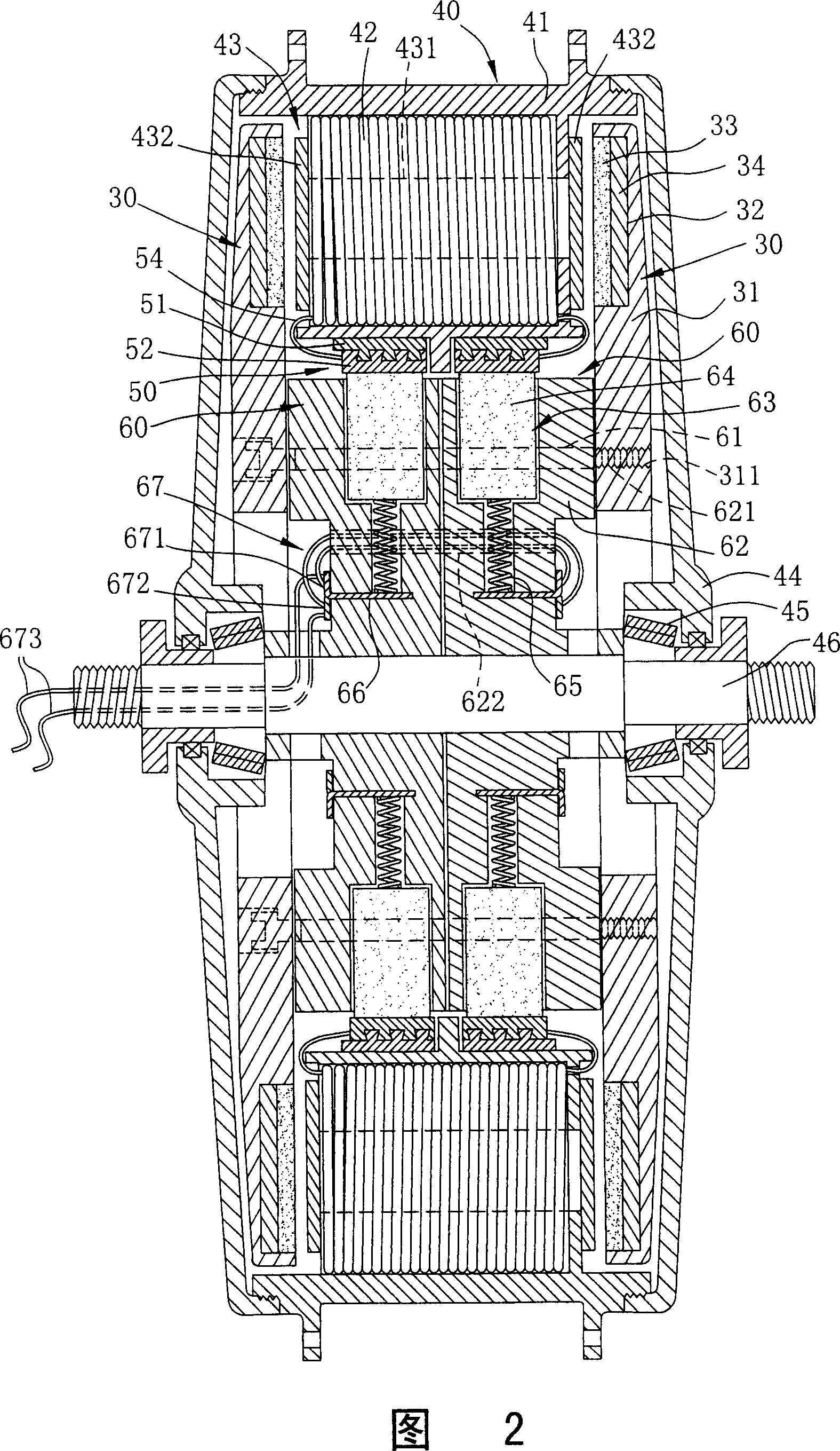
[0030] Fig. 2 is a schematic cross-sectional view of the first preferred embodiment of the motor structure of the present invention, which is mainly the structure of a brushed motor. As shown in the figure, the motor of the present invention mainly includes an inner armature 30 , an outer armature 40 , two commutators 50 , and two carbon brush sets 60 .

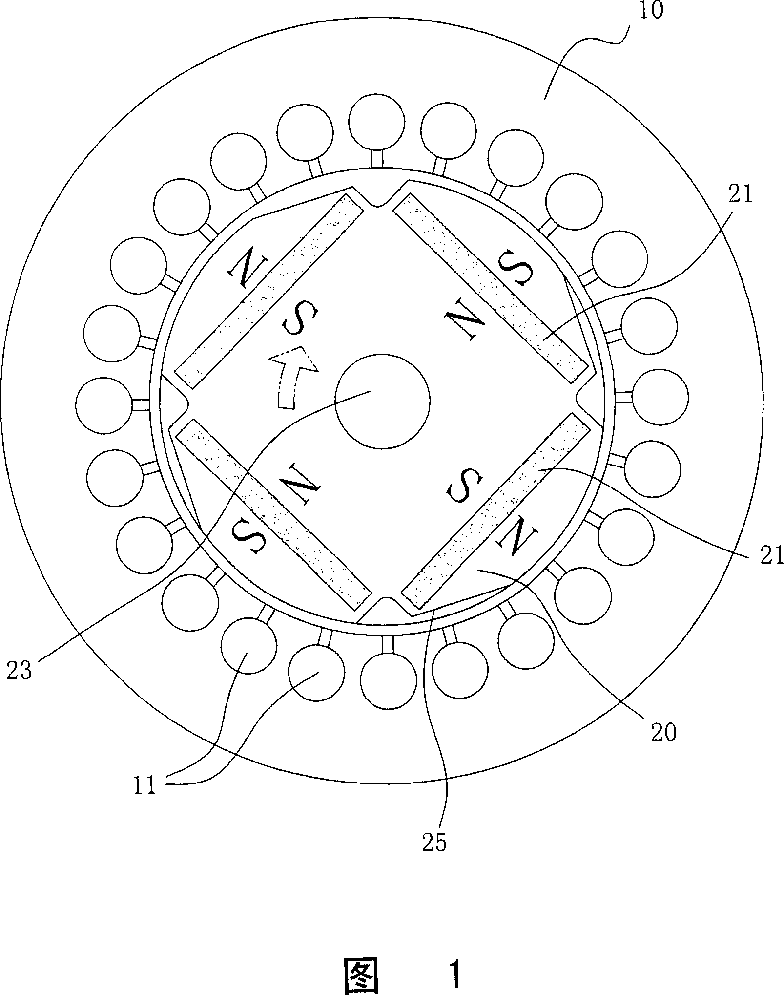
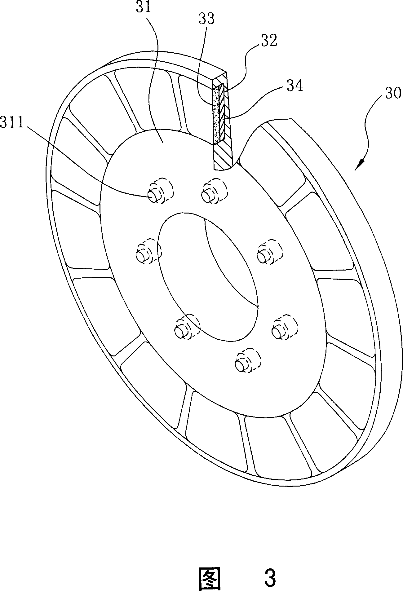
[0031] Please refer to FIG. 3 to FIG. 5 together. The inner armature 30 is provided with at least two layers of substrates 31, which are arranged opposite to each other. Hole 32 is established. Each of these installation holes 32 is embedded with a permanent magnet 33, so that two adjacent permanent magnets 33 have opposite magnetic poles; 33, the magnetic field lines of these permanent magn...


PUM


Abstract

The invention relates to a motor structure. The internal armature of the motor is provided in pivot with at least two foundation plates which are configured relative to each other at the front section and the rear section; each foundation plate is provided with a plurality of installation holes arranged in ring-like and is embedded with a permanent magnet; the two neighboring permanent magnets are of opposite magnet poles. While, the external armature of the motor is provided in pivot with a plurality of coils arranged in ring-like which are wound on a silicon steel plate group and relative to the permanent magnets of the two foundation plates. By resorting to relative rotation function of each coil to the front and rear sides of the permanent magnet, the invention enlarges the magnet line induced area and further increases the power output; the design of the suspension power supply (power-off) is applied to prevent the magnetic lag and save energy.

Description

technical field [0001] The invention relates to a structure of a motor, especially a design of increasing the induction area of ​​the magnetic force line and suspending power supply (cutting off) to prevent hysteresis, have power saving function, and increase the power output of the motor structure. Background technique [0002] The development of electric vehicles is changing with each passing day, but the most important factors affecting their performance are the torque and climbing ability of the electric motor (motor). Please refer to FIG. 1 , a general conventional motor includes a stator 10 (fixed armature) and a rotor 20 (moving armature). Among them, the inner edge of the stator 10 is embedded with a plurality of coils 11 at equal intervals, and these coils 11 are formed by winding enameled wires on stacked silicon steel sheet groups; The magnet 21 makes two adjacent permanent magnets 21 have opposite magnetic poles, so that when these coils 11 are energized to gene...

Claims


Application Information

Patent Timeline
IPC IPC(8): H02K1/17H02K1/27
Inventor 叶恩综叶东华
Owner 叶恩综
Why Eureka
Try Eureka