Seamless installation type sectional cabinet
A technology of seamless installation and combined cabinets, which is applied in the direction of combined furniture, household appliances, furniture parts, etc., can solve the problems of long construction period, need for on-site processing and installation, and troubles in the development of furniture modularization, so as to improve production efficiency and benefit, reduce The effect of production costs
- Summary
- Abstract
- Description
- Claims
- Application Information
AI Technical Summary
Problems solved by technology
Method used
Image
Examples
Embodiment 1
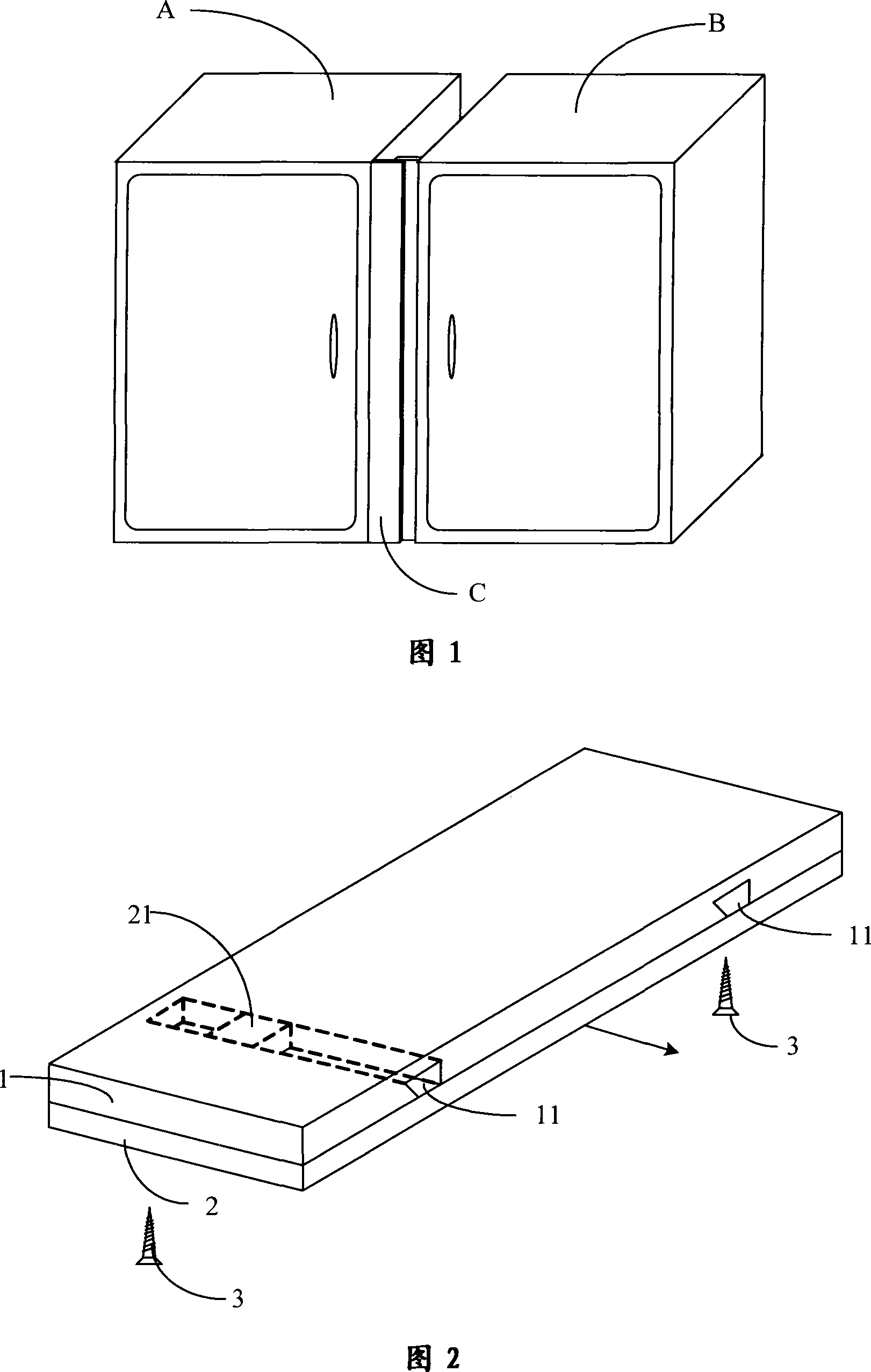
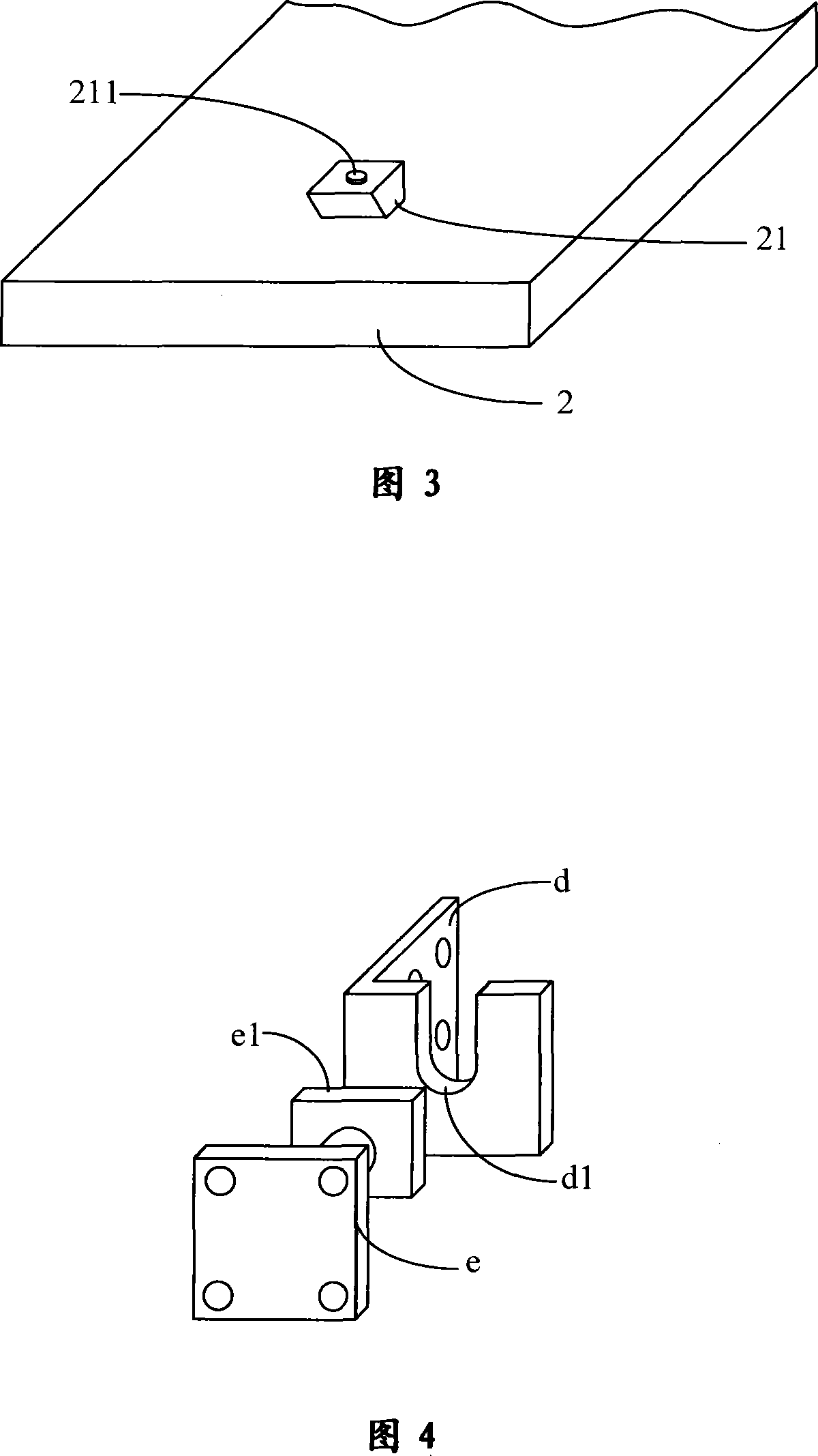
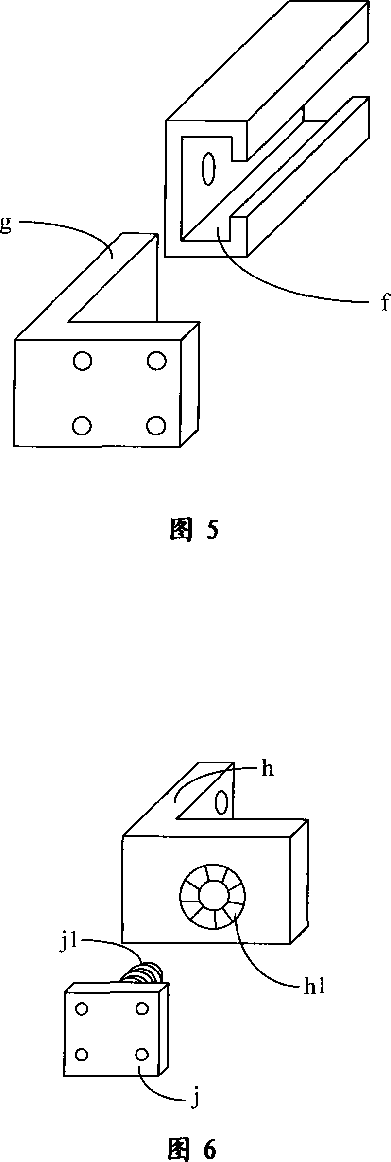
[0050] Figure 1 shows a specific embodiment of the present invention, which includes two independent boxes A and B arranged side by side. A panel C whose width can be adjusted is arranged between these two adjacent boxes (for the sake of clarity, the panel installed on the top is omitted in the figure), the structure of the panel C is as shown in Figure 2, including a decorative surface The surface layer 1 and the inner layer 2 with a decorative surface. Two dovetail-shaped slide grooves 11 are arranged on the back side of the surface layer 1 along the sliding direction shown by the arrow line in the figure, and two dovetail-shaped slide grooves 11 corresponding to the dovetail-shaped slide grooves 11 are arranged on the decorative surface of the inner layer 2. The slider 21. The slider 21 is matched and arranged in the chute 11 . The dovetail-shaped chute 11 and the slider 21 form a movement control part, which combines the surface layer 1 and the inner layer 2 together, an...
Embodiment 2
[0091] Fig. 23 shows the structure of another embodiment of the present invention. The figure is a common combination cabinet, which includes a wardrobe N erected on both sides, a TV cabinet K arranged in the middle of the bottom, and a locker M lying on the top of the wardrobe N. In the installation and combination of the combination cabinet, since the width and height dimensions of the site are larger than the actual combination size of the combination cabinet, in order to make the combination cabinet and the building "tightly fit", a panel C with adjustable width is adopted. In this embodiment, panel C adopts two specifications. The panel C installed between the wardrobe N and the adjacent TV cabinet K has two movable structures on the surface, and the panel C installed between the wardrobe N and the adjacent locker M has a movable inner layer. moving structure. In addition, two side panels C3 are arranged symmetrically on the left and right outer sides of the combined bo...
Embodiment 3
[0094] Fig. 24 shows the structure of another specific embodiment of the present invention, and this embodiment is that integral cabinet is installed on a wall surface of the kitchen. The combined width of the two top cabinets W in the figure is smaller than the width of the installation wall, and according to the installation requirements, the two top cabinets W are not allowed to touch the ceiling, so as to avoid the installation position being too high. In order to make the overall cabinet match the size of the installation environment, the panel C with adjustable width of the two movable inner layers is arranged between two adjacent top cabinets W, and on the upper part of the two top cabinets W An upper tooth plate C1 with a removable structure as the inner layer is arranged on the outside to connect with the ceiling, so that this problem can be solved satisfactorily without any secondary processing on site. Same as the above-mentioned second embodiment, this embodiment a...
PUM
 Abstract
Description
Claims
Application Information
 - R&D
- Intellectual Property
- Life Sciences
- Materials
- Tech Scout
- Unparalleled Data Quality
- Higher Quality Content
- 60% Fewer Hallucinations
Browse by: Latest US Patents, China's latest patents, Technical Efficacy Thesaurus, Application Domain, Technology Topic, Popular Technical Reports.
© 2025 PatSnap. All rights reserved.Legal|Privacy policy|Modern Slavery Act Transparency Statement|Sitemap|About US| Contact US: help@patsnap.com


