Heat shaped machine exhaust heat air purification heat energy utilized heat pipe exchanger

A technology of heat pipe heat exchanger and hot air, which is applied in chemical instruments and methods, steam/steam condensers, lighting and heating equipment, etc., and can solve problems such as large pressure loss, environmental pollution, and polluted environment

Inactive Publication Date: 2008-01-30
吴江市普天热管技术推广应用研究所
View PDF0 Cites 34 Cited by
  • Summary
  • Abstract
  • Description
  • Claims
  • Application Information

AI Technical Summary

Problems solved by technology

[0002] In the textile printing and dyeing industry, the heat setting machine is a large energy consumer; the temperature of the hot air used by the heat setting machine is 200-230°C, and the temperature of the waste heat air discharged after the consumption of the shaped fabric is 180-200°C, and contains a relatively high concentration of yarn dust And heat setting machine running lubricating oil steam, high-temperature waste heat air containing dust and oil is directly discharged into the atmosphere, wasting 90% of low-grade heat energy and polluting the environment; currently, the devices for recovering heat setting machine waste heat air include rotary type, tube type and Plate heat exchanger, but there are generally disadvantages such as low recovery efficiency, large pressure loss, easy blockage, and difficult cleaning; there are also a small number of reports on the use of heat pipe heat exchangers to recover the heat of waste air, but the above-mentioned various heat recovery devices have not solved the problem. yarn dust and oil vapor pollution, but cannot be popularized, resulting in environmental pollution and a lot of energy waste

Method used


Image

  • Heat shaped machine exhaust heat air purification heat energy utilized heat pipe exchanger

Examples


Embodiment Construction

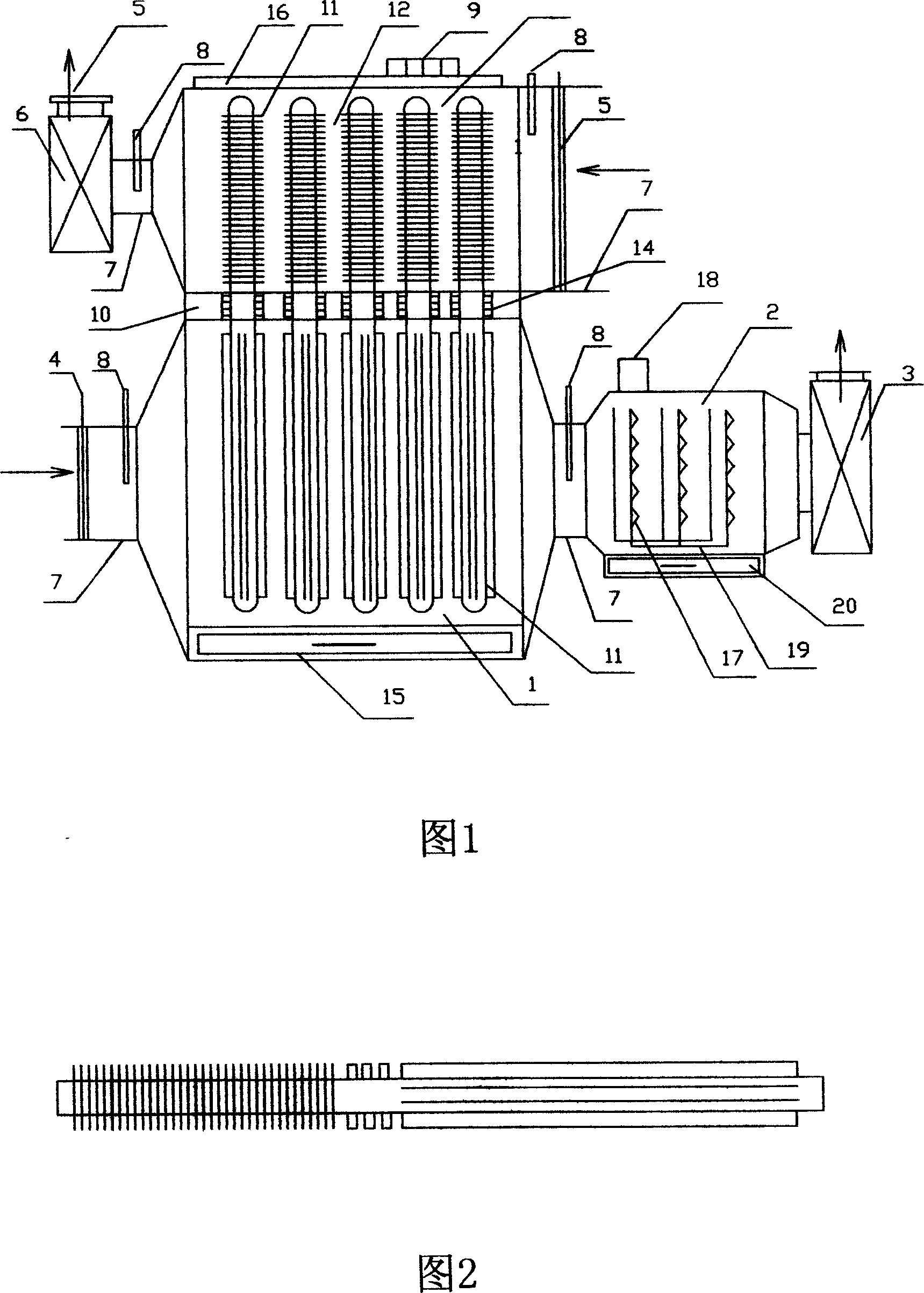
[0012] In figure (1), the top of the tube plate (10) of the heat pipe heat exchanger (1) is an air heating chamber (12) with a top cover (16), the bottom is a waste heat air heat absorption chamber (13), and the heat pipe (11 ) is inserted into the fork hole of the tube plate (10) with a tapered snap ring (14) asbestos climbing root, and under the action of the induced draft fan (3), the waste hot air containing yarn dust oil vapor is inserted through the detachable dust filter. The tank (4) temperature sensor (8) passes through the air inlet and outlet pipe (7) to the waste heat air absorption chamber (13), and the heat absorbed by the heat absorption section of the longitudinal finned heat pipe (11) is phase-transformed and transferred to the upper air of the tube sheet (10) In the heat release section of the spiral fins in the heating chamber (12), the temperature of the waste heat air drops rapidly, and the oil vapor is condensed on the longitudinal fins and removed, and fl...


PUM


Abstract

A heat pipe heat exchanger for waste heat air purifying and heat energy utilization of heat setting equipment is a heat pipe heat exchanger that is provided with heat pipes of different working mediums. An exothermic section of an air side heat pipe is of a spiral fin structure, and an endothermic section of a waste heat air side heat pipe is of a longitudinal fin structure. 50 percent of heat energy is recycled when the temperature of the waste heat air falls from 180 DEG C to 70-80 DEG C. At the same time, a waste heat air inlet tube and a heated air inlet tube are provided with a slot with a detachable and replaceable yarn dust filtering netting; the steamed and liquidized air that is condensed and discharged from the waste heat air with the heat absorbed by the heat pipe of longitudinal fin structure flows into an oil sump tank along the longitudinal fin, enters a low temperature electrostatic pulse oil fume staticizer, and the oil molecular is ionized in the high pressure pulse positive-negative electrode electric field. The waste heat air discharged from the heat setting equipment fundamentally reaches the requirements of environment protective of low temperature, dust free and oil free.

Description

technical background [0001] The invention belongs to a heat pipe device for purifying high-temperature exhaust gas, dust oil and recycling heat energy of heat setting machines in the textile printing and dyeing industry. Background technique [0002] In the textile printing and dyeing industry, the heat setting machine is a large energy consumer; the temperature of the hot air used by the heat setting machine is 200-230°C, and the temperature of the waste heat exhausted after the finished fabric is consumed is 180-200°C, and contains a relatively high concentration of yarn dust And heat setting machine running lubricating oil steam, high-temperature waste heat air containing dust and oil is directly discharged into the atmosphere, wasting 90% of low-grade heat energy and polluting the environment; currently, the devices for recovering heat setting machine waste heat air include rotary type, tube type and Plate heat exchangers, but there are generally disadvantages such as lo...

Claims


Application Information

Patent Timeline
Patent Type & Authority Applications(China)
IPC IPC(8): F28B3/00B03C3/00
Inventor 朱友良凌峰
Owner 吴江市普天热管技术推广应用研究所
Why Eureka
Try Eureka