Magnetic head

A technology of magnetic head and read head, which is applied in the direction of magnetic recording head, magnetic head using thin film, supporting head, etc., which can solve the problems of increasing Coulomb force, damage of magnetic head actuator balance, and inability to effectively heat and protrude the surface side of the medium

Inactive Publication Date: 2008-01-30
FUJITSU LTD
View PDF3 Cites 0 Cited by
  • Summary
  • Abstract
  • Description
  • Claims
  • Application Information

AI Technical Summary

Problems solved by technology

[0003] Such a conventional magnetic head incorporating a heater has a problem in that the heat generated by energizing the heater coil is transferred to the substrate side of the magnetic head formed as a slider, and is dispersed to the medium-facing surface, so that the medium-facing surface side Cannot be effectively heated and protruded, on the side facing the medium surface is provided a write gap functioning as a recording element of the write head and a read gap provided with a read element
Therefore, there is a problem in which the area where the Coulomb force is formed between the facing area on the head side and the medium increases, the Coulomb force is increased, and the balance of the head actuator is broken so that the head is pressed against by a strong force on the surface of the medium

Method used


Image

  • Magnetic head
  • Magnetic head
  • Magnetic head

Examples


Embodiment Construction

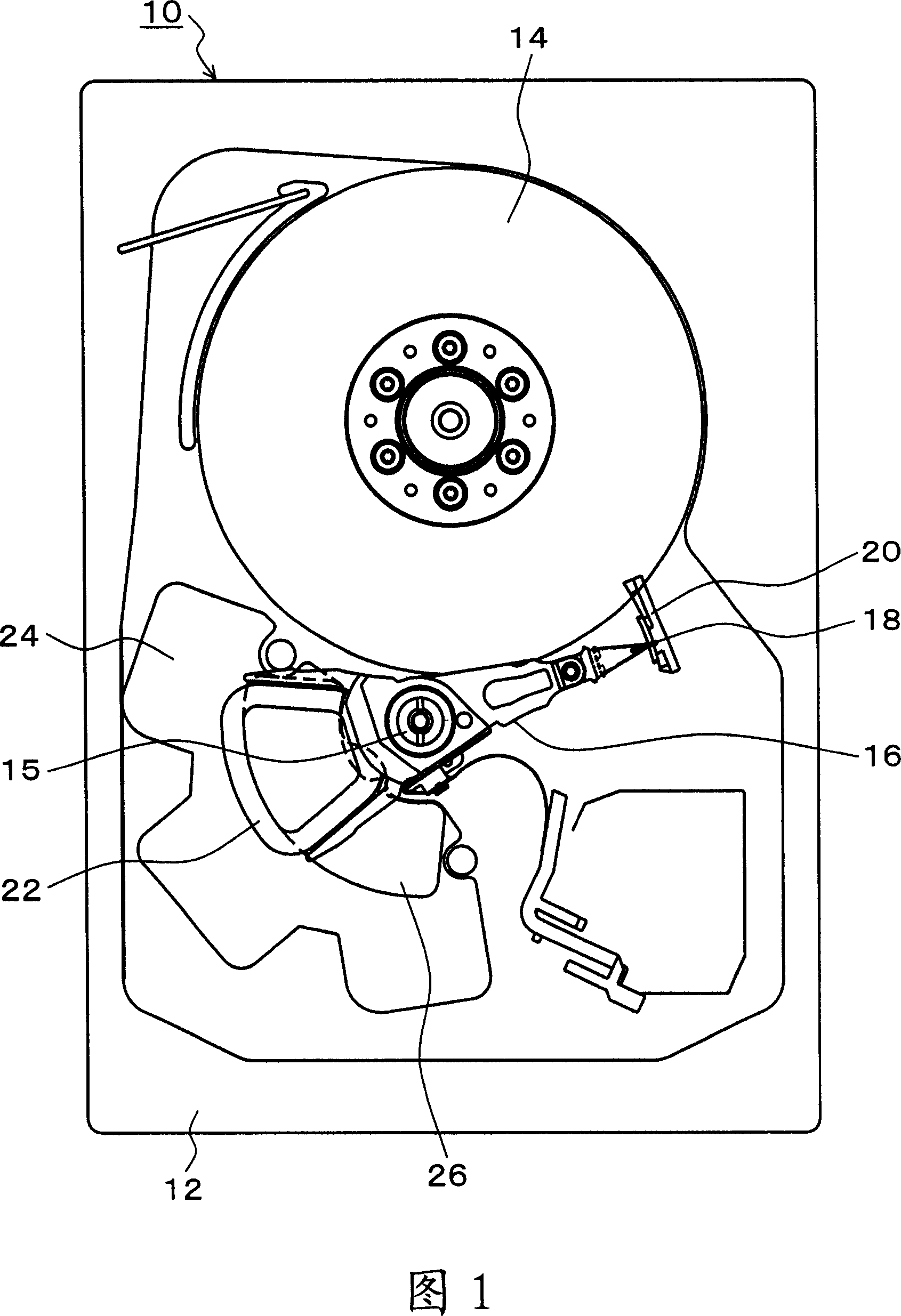
[0044] FIG. 1 is an explanatory diagram of a magnetic disk device using a magnetic head of the present invention. In FIG. 1 , the internal structure of the chassis bottom plate 12 with the chassis cover removed from the magnetic disk unit 10 is shown. A magnetic disk 14 rotated at a constant speed by a spindle motor is disposed in the chassis bottom plate 12 , and a rotary actuator 16 is rotatably provided for the magnetic disk 14 through a shaft unit 15 . The rotary actuator 16 supports the magnetic head according to the present invention by its end, and the coil 22 is provided at the rear of the rotary actuator 16 . The coil 22 is rotatable along a magnet 26 on a lower yoke 24 fixed to the side of the cabinet bottom plate 12 . Although an upper yoke, which is not shown and has the same shape as the lower yoke 24, is provided above the coil 22, a state where the upper yoke is removed is shown in this embodiment. The magnetic circuit unit is formed by a lower yoke 24, a magn...


PUM

PropertyMeasurementUnit
thicknessaaaaaaaaaa
thicknessaaaaaaaaaa

Abstract

The present invention provides a magnetic head, which has a read head and a write head on a substrate. In the read head, a read element that converts recording magnetic flux emitted from a magnetic disk into an electrical signal is arranged between a pair of protective layers. The head magnetically records information by sending a magnetic flux generated by a write current flowing through the write coil from the pole unit to the magnetic disk. A heater coil is provided to face the writing coil through an insulating layer, and causes a medium-facing surface to protrude toward the recording medium side by energization and heating. Next to the protective layer on the side of the substrate, a low thermal conductivity layer and a low thermal expansion layer made of a material having a low thermal conductivity that suppress generation of electricity due to energization and heating of the heater coil are provided. conduction of heat, the low thermal expansion layer is disposed on the substrate side of the low thermal conductivity layer, and is made of a material having a low thermal expansion coefficient.

Description

technical field [0001] The present invention relates to a magnetic head capable of controlling the gap between the magnetic head and a recording medium by changing the protrusion distance of the surface facing the medium by thermal expansion accompanied by energization and heating of a heater coil, and more particularly, the present invention relates to A magnetic head that can achieve a larger protrusion distance facing the surface of a medium by a smaller electric power of a heater coil. Background technique [0002] Conventionally, it was necessary to reduce the flying height of the magnetic head relative to the recording surface of the magnetic disk in order to realize a high recording density of the magnetic disk device; and recently, a flying height of the order of 10 nm has been realized. However, when the flying height of the magnetic head is reduced, the problem of colliding with tiny protrusions on the magnetic disk surface is prone to occur, so that the variation ...

Claims


Application Information

Patent Timeline
Patent Type & Authority Applications(China)
IPC IPC(8): G11B5/127G11B5/17G11B5/60G11B21/21
CPCB82Y10/00G11B5/5552G11B5/3967G11B5/3136G11B5/3909G11B5/3912B82Y25/00G11B5/314G11B5/6011G11B2005/3996G11B5/127G11B5/31G11B5/60G11B21/21
Inventor 青木健一郎中田敏幸
Owner FUJITSU LTD
Why Eureka
Try Eureka