Power source converter and transformer

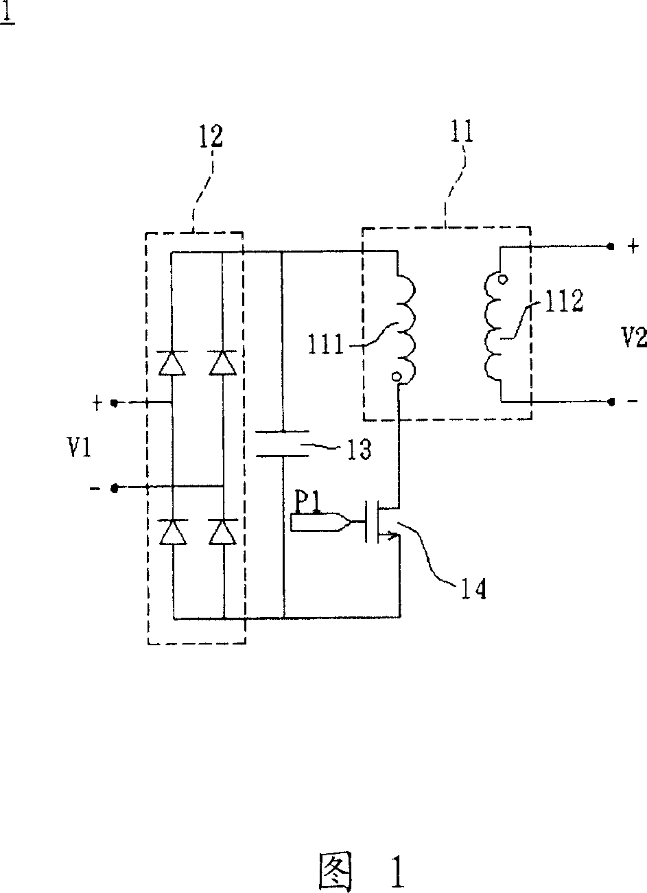
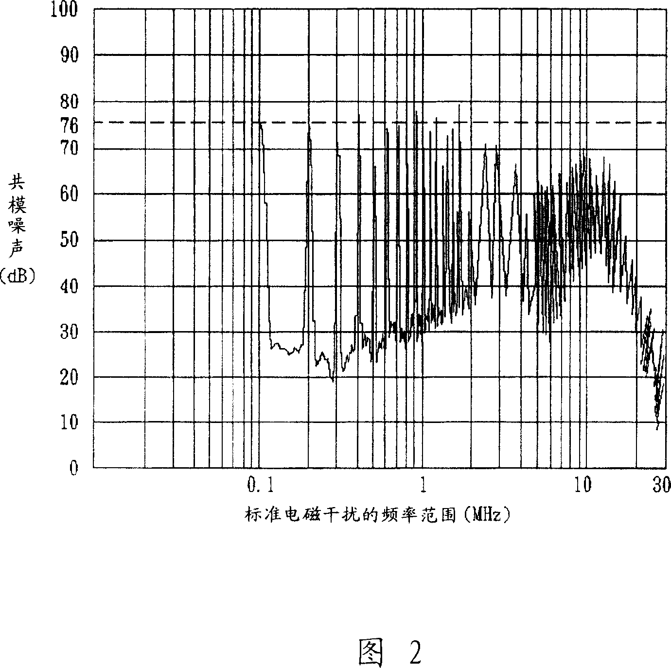
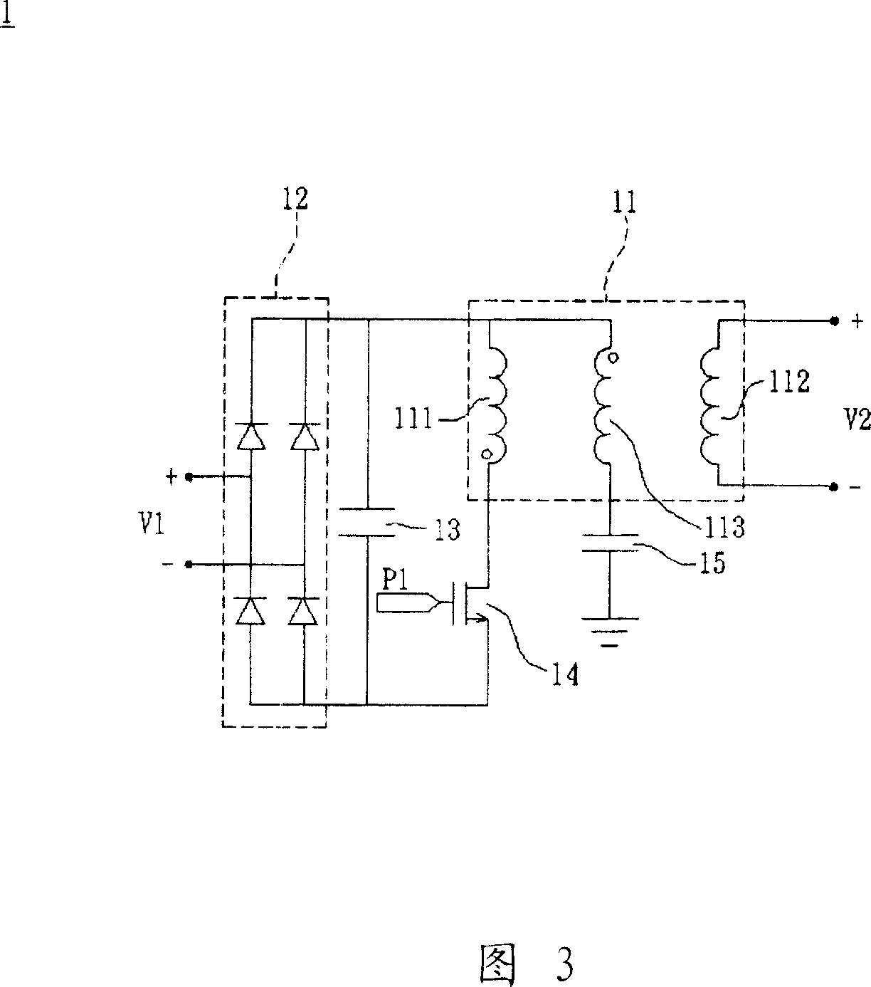
A power conversion and transformer technology, applied in the direction of output power conversion devices, electrical components, preventing/reducing unwanted electric/magnetic effects, etc., can solve the difficulty of suppressing common mode noise and increase the capacitance value of the secondary side winding 112 and other issues to achieve the effect of reducing common mode noise, reducing volume and cost, and improving performance

Active Publication Date: 2008-01-30
DELTA ELECTRONICS INC
View PDF0 Cites 14 Cited by
  • Summary
  • Abstract
  • Description
  • Claims
  • Application Information

AI Technical Summary

Problems solved by technology

However, this method increases the capacitance value of the secondary side winding 112 to

Method used


Image

  • Power source converter and transformer
  • Power source converter and transformer
  • Power source converter and transformer

Examples


Example Embodiment

[0040] Hereinafter, a power conversion device and its transformer according to a preferred embodiment of the present invention will be described with reference to related drawings, wherein the same components will be described with the same reference signs.

[0041] Referring to FIGS. 5 and 6, a transformer 2 according to a preferred embodiment of the present invention includes a magnetic component 21, a first winding 22, a second winding 23, and a shielding component 24. The transformer 2 can be applied to A switching power supply device or an inverter. In this embodiment, the material of the magnetic component 21 is not limited, such as magnets, magnets or magnetic tapes, and the shape of the magnetic component 21 is also not limited. Here, a cylindrical shape is taken as an example.

[0042] The first winding 22 is wound outside the magnetic component 21, and the second winding 23 is wound outside the first winding 22; the first winding 22 and the second winding 23 can be wound...


PUM


Abstract

A transformer includes a magnetic component, a first winding group, a second winding group and a shielding component. The first winding group is windingly arranged on the magnetic component. The second winding group is windingly arranged on the first winding group. The shielding component is arranged between the first winding group and the second winding group.

Description

technical field [0001] The invention relates to a power conversion device and a transformer thereof. Background technique [0002] In recent years, electronic circuits are widely used in electronic devices, such as power conversion devices, that is, power supplies or power converters. However, since such circuits are often operated at high frequency switching, it is easy to generate Electro-Magnetic Interference (EMI), which further affects electronic devices. According to different transmission methods, EMI can be classified as Radiant There are two types of conduction (Conducted), radiated electromagnetic interference is transmitted directly from the open space, and conductive electromagnetic interference is transmitted through wires. [0003] Conducted electromagnetic interference can be divided into common-mode noise and differential-mode noise according to the different conduction paths of the noise current. The differential-mode noise is when the current directions of...

Claims


Application Information

Patent Timeline
IPC IPC(8): H01F27/34H01F27/36H01F27/38H02M7/06H02M7/537
Inventor 卢增艺陈为
Owner DELTA ELECTRONICS INC
Why Eureka
Try Eureka