Apparatus for simulating flames with reflection type infrared heater

An infrared heater and flame simulation technology, applied in portable lighting devices, lighting devices, non-electric lighting devices, etc., can solve the problems of unfavorable health, energy saving, and uncomfortable feeling of users, and achieve production and after-sales service Low cost, save valuable space, wide application effect

Inactive Publication Date: 2008-02-06
杜仁委
View PDF2 Cites 12 Cited by
  • Summary
  • Abstract
  • Description
  • Claims
  • Application Information

AI Technical Summary

Problems solved by technology

It is known that the flame simulation device is generally combined with an electric fan heating device. The device sucks air from each vent and blows it into the room after being heated. After a long time, a lot of dust will be sucked in and blown back into the room without any treatment. , which is not conducive to the health of the user. For example, Chinese Patent Application No. 200310122956.0 discloses a flame simulation device applied to an electric fireplace, which includes an electric heater
In order to solve this problem, Chinese Patent Application No. 200610008599.9 provides a flame simulation device including a filter, but the structure is extremely complicated, and it needs to be dismantled and cleaned frequently, which is very inconvenient. It is radiation heat transfer, and the human body feels more comfortable. It is not comfortable to use electric fan for heating, and it does not conform to the actual fire heat transfer method. No matter how realistic the simulated flame is, it still feels fake
The traditional flame simulation device uses ordinary light bulbs to emit light, which is not energy-saving, and the flame shape is relatively rigid and single. Therefore, it is necessary to have a simpler structure, low noise, and will not blow out dust into the room. It is energy-saving and environmentally friendly, and can more realistically simulate real flame transmission. Thermal Flame Simulator

Method used


Image

  • Apparatus for simulating flames with reflection type infrared heater
  • Apparatus for simulating flames with reflection type infrared heater
  • Apparatus for simulating flames with reflection type infrared heater

Examples


Embodiment Construction

[0025] Preferred Example Details

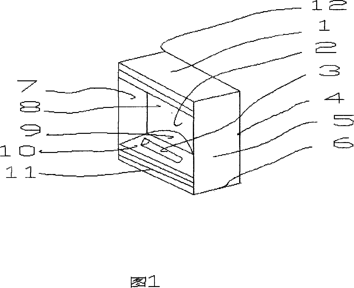
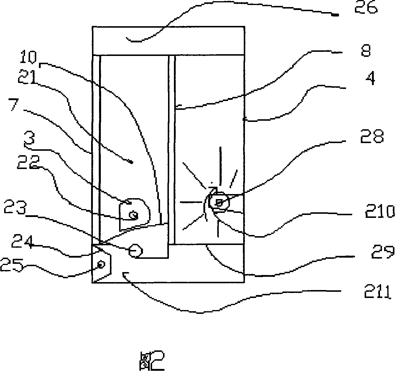
[0026] Fig. 1 is the appearance perspective view of the present invention, and its shell 12 is made up of front 2, back 4, upper top 1, lower bottom 2 and side 5, front transparent glass fiber reinforced plastic 7, base 10, imaging screen 8 and side panel 5 encircle closed space Composition simulation hearth 21 (see Fig. 2), base 10 is placed with simulation wood or charcoal 3, and the top or bottom of front 2 is equipped with anti-scald grille 11.

[0027] It can be seen from Fig. 1 and Fig. 2 that the simulated furnace 21 is composed of a closed space surrounded by front transparent glass steel 7, base 10, imaging screen 8 and side panels 5, and the base 10 and simulated wood or charcoal 3 are made of translucent plastic , at least one LED light 23 is placed under the base, and at least one LED light is placed in the simulated wood block or charcoal. The LED light can flicker and gradually brighten and fade to simulate the flickering of car...


PUM


Abstract

The present invention provides a flame simulating device, which comprises a hexahedron casing, a simulation hearth which is arranged on the middle-front part of the casing, an image formation screen which is arranged in the center place of the inner casing, a dynamical flame shaped light beam producing component arranged behind the image formation screen, and an infrared ray heater with a reflecting cover. The front face of the hexahedron casing is transparent, and directs to the user for looking at the simulated flame; the infrared ray heater uses radiation to transfer the heat, and concentrates the heat. The dynamical flame shaped light beam producing component is a rotating luminous tube, which can produce the flame shaped light beam, the image is formed on the reverse side of the image formation screen, and transmitted on the front surface of the image formation screen, along with the rotating of the luminous tube, the flame shaped image rises slowly as a real flame. Meanwhile, the infrared ray heater transfers the heat by radiation, thereby giving people a real feeling like around the fire place.

Description

field of invention [0001] The invention relates to a flame simulating device with a reflective heater capable of simulating real flames and having real flame thermal sensation, which can be applied to electric fireplaces, electric stoves and other products requiring simulated flames. Background of the invention [0002] Traditional fireplaces and stoves burn charcoal or wood. Due to the complexity and high cost of solving the gas and soot produced after combustion, electric fireplaces and electric stoves that simulate traditional fireplaces and stoves are more and more popular. It is known that the flame simulation device is generally combined with an electric fan heating device. The device sucks air from each vent and blows it into the room after being heated. After a long time, a lot of dust will be sucked in and blown back into the room without any treatment. , which is not conducive to the health of the user. For example, Chinese Patent Application No. 200310122956.0 dis...

Claims


Application Information

Patent Timeline
IPC IPC(8): F21S10/04F21V1/14F21V14/02H05B37/02F21W121/00F21Y101/02F21Y115/10
Inventor 杜仁委
Owner 杜仁委
Why Eureka
Try Eureka