Light scattering detector

A detector and light scattering technology, applied in scattering characteristics measurement, instruments, measurement devices, etc., can solve the problems of troublesome operation, unable to obtain correct results, etc., and achieve the effect of simple measurement operation

Inactive Publication Date: 2008-02-06
SHIMADZU SEISAKUSHO CO LTD
View PDF2 Cites 58 Cited by
  • Summary
  • Abstract
  • Description
  • Claims
  • Application Information

AI Technical Summary

Problems solved by technology

This makes the operation cumbersome, and if re-measurement is difficult to perform due to precious or scarce samples, correct results may not be obtained

Method used


Image

  • Light scattering detector
  • Light scattering detector
  • Light scattering detector

Examples


Embodiment Construction

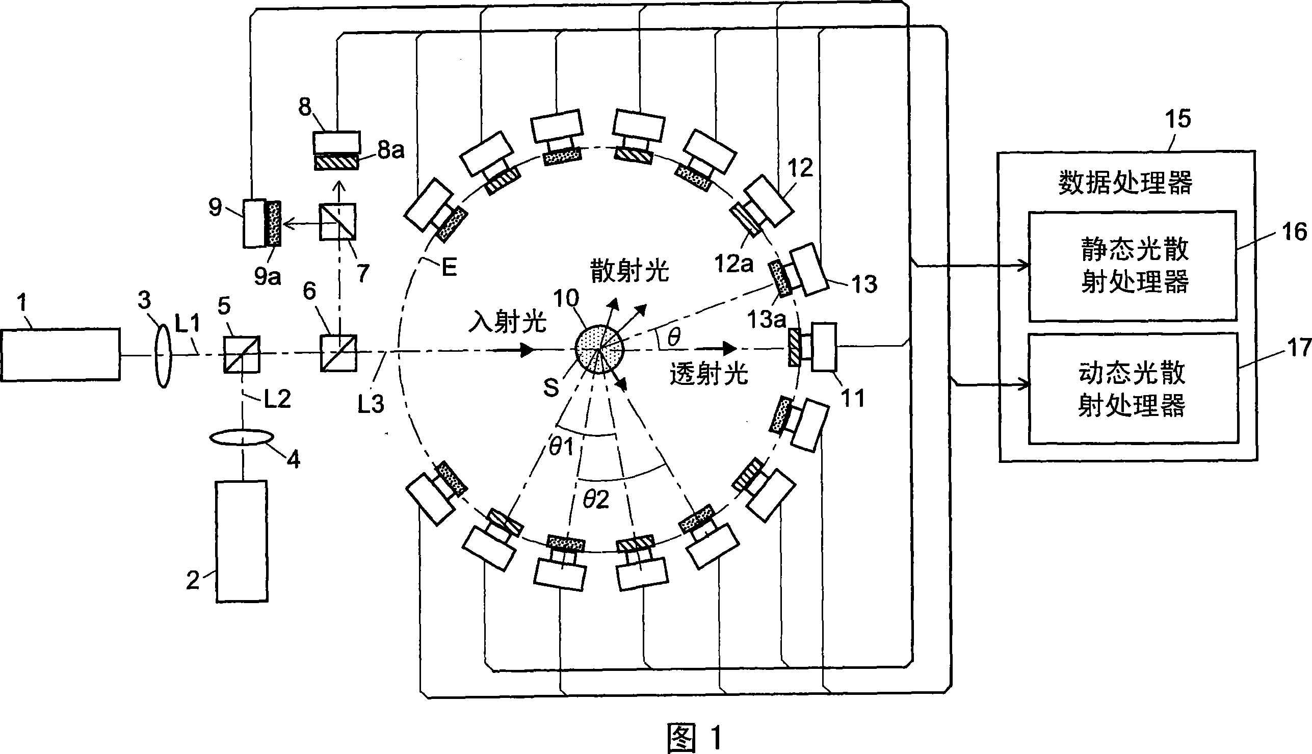
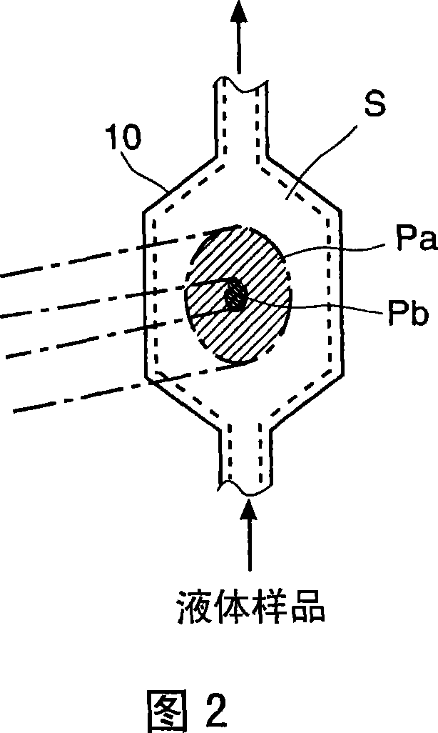
[0068] First, a hybrid light-scattering detector as an embodiment of the light-scattering detector of the first aspect of the present invention will be described with reference to the drawings. FIG. 1 is an overall block diagram of the hybrid light scattering detector of this embodiment, and FIG. 2 shows the state of incident light in a sample cell.

[0069] In the hybrid light scattering detector of this embodiment, the sample cell 10 is placed in the center of the circle E. The sample cell 10 is a flow cell having a transparent wall for supplying a liquid sample S therein. (As the sample cell 10, other cells such as square cells and test tube cells for holding liquid samples can be selectively used.) On circle E, a transmitted light detector 11, a plurality of static light scattering detectors, and a plurality of dynamic light Scatter detectors are placed around the sample cell 10 . A plurality of static light-scattering detectors 12 are placed at predetermined angular int...


PUM

PropertyMeasurementUnit
sizeaaaaaaaaaa

Abstract

The light scattering detector according to the present invention aims at simultaneously measuring the molecular weight and size of particles having varieties of diameters. This detector facilitates the measurement operation and knowing how particles associate or dissociate as time progresses. In this detector, the emitted light (static light scattering measurement light) having a first wavelength by the first light source and the emitted light (dynamic light scattering measurement light) having a second wavelength which is different from the first wavelength by the second light source are combined by a beam splitter 5 and coaxially directed onto the sample sell 10 to which a liquid sample S is supplied. While the irradiated area by the static light scattering measurement light is large, the irradiated area by the dynamic light scattering measurement light, which is coherent light, is narrow. Detectors 12 which selectively detect the first wavelength and detectors 13 which selectively detect the second wavelength are placed so as to encircle the sample cell 10. The detection signals by the detectors 11, 12 and the detection signals by the detectors 13 are separately mathematically-operated by a data processor 15 to calculate the molecule weight and size of the particles in the sample S.

Description

technical field [0001] The present invention relates to a light scattering detector for use in a microscopic particle detector for measuring molecular weight and size such as radius of gyration of microscopic particles dispersed in a liquid sample. Background technique [0002] Typically, components with large molecular weights, insoluble polymers, or microscopic particles are difficult or impossible to separate by liquid chromatography. As methods for separating such substances, for example, gel permeation chromatography (hereinafter, abbreviated as GPC) and field flow fractionation (hereinafter, abbreviated as FFF) are known. Also, as a detector of microscopic particles separated by GPC or FFF, a multi-angle light scattering detector based on the principle of the static light scattering method is generally used (for example, see Patent Documents 1 and 2 ). Multi-angle light scattering detectors are capable of simultaneously detecting light exiting a sample at several dif...

Claims


Application Information

Patent Timeline
Patent Type & Authority Applications(China)
IPC IPC(8): G01N15/14G01N15/02G01N21/51
CPCG01N2015/0092G01N15/0205
Inventor 大久保邦彦
Owner SHIMADZU SEISAKUSHO CO LTD
Why Eureka
Try Eureka