Offset air current powder needle split charging head device

An offset, airflow technology, applied in the directions of packaging, transportation and packaging, and the type of packaged items, can solve the problems of the large outer circle size of the airflow powder needle dispensing head, the large size of the machine, and the large workload of the powder cartridge. To achieve the effect of easy cleaning of the powder cartridge and metering brush, reduced weight and small moment of inertia

Active Publication Date: 2008-02-13
TRUKING TECH LTD
View PDF0 Cites 0 Cited by
  • Summary
  • Abstract
  • Description
  • Claims
  • Application Information

AI Technical Summary

Problems solved by technology

[0002] In the prior art, the air-flow powder needle dispensing head parts of the air-flow powder needle dispensing machines used in the domestic and foreign markets are divided into single-head and double-head two types, and the powder cylinders are generally placed on the circumference of the air-flow powder-filling head. Symmetrical (that is, centered) distribution. Due to the restriction of the specific height of the powder cylinder, this arrangement makes the outer circle of the airflow powder needle dispensing head larger (generally more than 300 mm in outer diameter), large in mass, and large in inertia. Machine dimensions are also larger
At the same time, in order to make full use of the space in the outer circle, there are as few as a dozen (single row) and more than 20 (double rows) of powder cylinders, which brings considerable workload to the installation, debugging and cleaning of the powder cylinders.

Method used


Image

  • Offset air current powder needle split charging head device
  • Offset air current powder needle split charging head device
  • Offset air current powder needle split charging head device

Examples


Embodiment 1

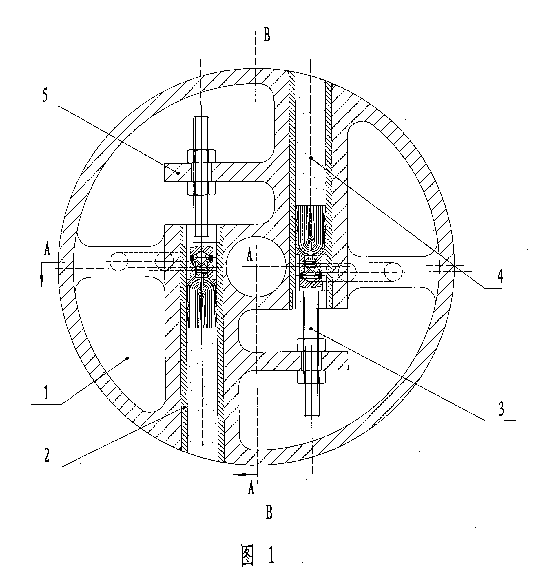
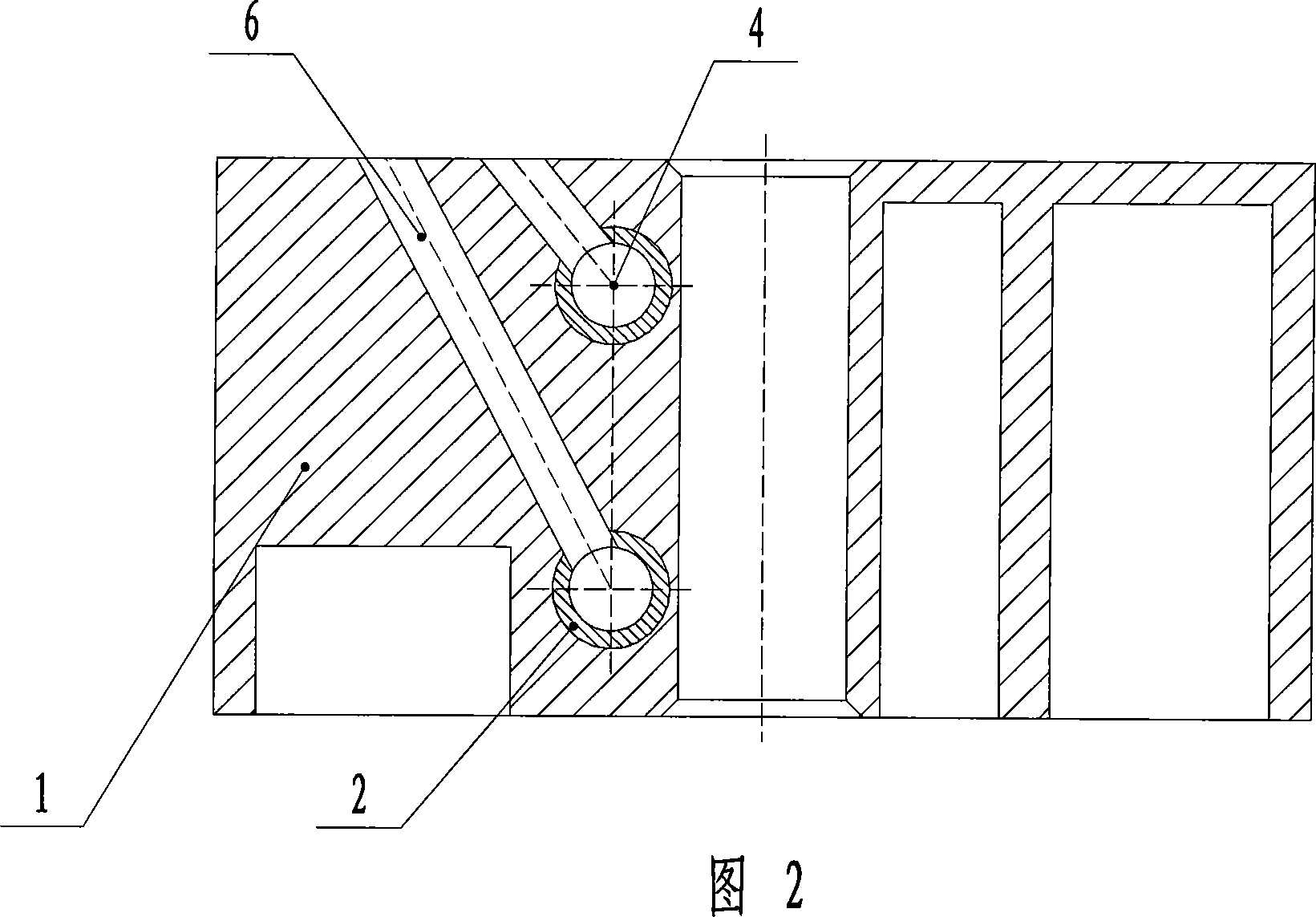
[0019] Example 1: As shown in Figure 1 and Figure 2, the line BB in the figure is the radial centerline of the airflow powder injection dispensing head 1. The axis of the powder cylinder 4 of the airflow powder injection dispensing head 1 is based on the airflow powder injection dispensing head 1. The BB line of the mounting head 1 is parallel to the center reference line, and the upper and lower lines are equally offset. That is to say, the circumference of the air jet powder injection dispensing head is divided into two powder cylinders 4 at 180°, which is suitable for use on a single-row powder injection dispensing machine that dispenses one bottle at a time.

Embodiment 2

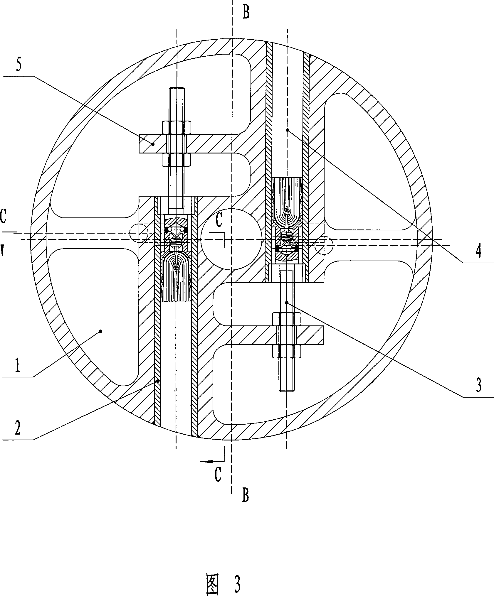
[0020] Example 2: As shown in Fig. 3 and Fig. 4, the axis line of the powder cylinder 4 of the airflow powder injection dispensing head 1 is centered on the BB line of the airflow powder injection dispensing head 1 and the reference lines are parallel to each other. It means that two pairs of powder cylinders 4 are divided equally at 180° on the circumference of the airflow powder injection dispensing head 1. It is suitable for use on a double-row powder injection dispensing machine that dispenses two bottles at a time. The machine uses star wheel intermittent bottle feeding, it feeds two bottles at a time, so the central connecting line of the two powder cartridges 4 is parallel to the axis line of the airflow powder injection dispensing head 1, and the center distance is parallel to the matching bottle feeding star. The pitches of the gear teeth are equal.


PUM


Abstract

The present invention discloses a side-located filling head device of an airflow powder injection, comprising the filling head of the airflow powder injection, a computation brush, a powder cylinder and a powder cylinder sleeve arranged on the filling head of the airflow powder injection. The computation brush and the powder cylinder are arranged in the powder cylinder sleeve, in which an air flue communicates with an air source is arranged. The axial line of the powder cylinder is arranged parallely and symmetrically, taking the radial central line of the filling head of the airflow powder injection as the central datum line. The present invention has the advantages of simple and compact structure, small size, light weight, low manufacture cost, simple installation and debugging and convenient cleaning and debugging.

Description

Technical field [0001] The invention mainly relates to the field of medical filling equipment, and particularly refers to a biased airflow powder injection dispensing head device. Background technique [0002] In the prior art, the airflow powder injection dispensing head components of the airflow powder injection dispensing machine used in the domestic and foreign markets are divided into two types, single-head and double-headed, and the powder cylinder is generally on the circumference of the airflow dispensing head. The upper symmetrical (ie centering) distribution, due to the restriction of the specific height of the powder tube, this arrangement makes the outer diameter of the airflow powder needle dispensing head larger (generally more than 300 mm in outer diameter), large mass, large moment of inertia, The size of the machine is also larger. At the same time, in order to make full use of the outer space, there are as few as a dozen powder cartridges (single row), and as ma...

Claims


Application Information

Patent Timeline
Patent Type & Authority Applications(China)
IPC IPC(8): B65B1/16B65B1/30
Inventor 段志敏刘振李鹏程唐岳
Owner TRUKING TECH LTD
Why Eureka
Try Eureka