Back penetration measuring method for film base binding performance

A technology that combines performance and measurement methods, applied in the field of measurement, can solve problems such as complex prefabrication of parts to be tested, substrate systems limited by silicon materials, etc.

Inactive Publication Date: 2008-02-13
SHANGHAI JIAO TONG UNIV
View PDF1 Cites 10 Cited by
  • Summary
  • Abstract
  • Description
  • Claims
  • Application Information

AI Technical Summary

Problems solved by technology

The invention solves the technical problems of complex prefabrication of the parts to be tested and the limitation of the substrate system by the silicon material in the prior art, can quantitatively measure the bonding performance of the membrane base, accurately measure the bonding force of the membrane base, and obtain the fatigue performance parameters of the membrane

Method used


Image

  • Back penetration measuring method for film base binding performance
  • Back penetration measuring method for film base binding performance
  • Back penetration measuring method for film base binding performance

Examples


Embodiment 1

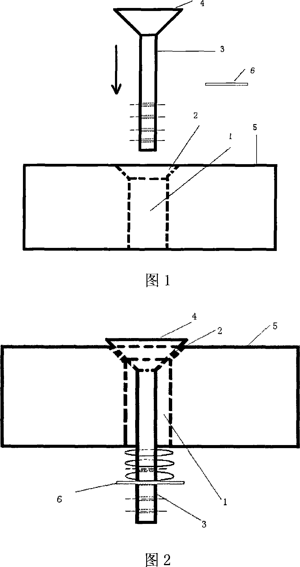
[0026] Step 1: Machining a round through hole 1 with a radius of 1.5mm on a substrate with a size of 40mm×20mm×5mm, and machining a chamfer 2 of 45° as shown in FIG. 1 on the through hole.

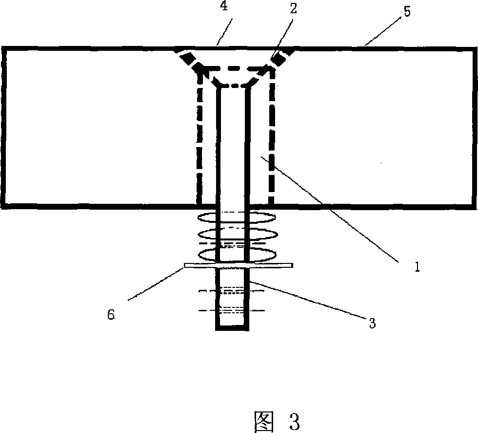
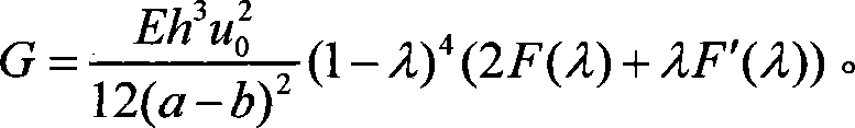
[0027] The second step: process a matching ejector pin 3 . As shown in FIG. 2 , the top end surface 4 of the ejector rod in the assembled base system is 0.75 mm higher than the base coating surface 5 , and the coating surface is ground as shown in FIG. 3 . Ensure that the coating surface is flat and smooth.

[0028] Step 3: Cover the lower end of the ejector rod with a spring with a radius 0.5 to 1mm larger than that of the base hole and have a higher rigidity. Between the plug pin 6 and the base, thus making the ejector pin and the base in a tight contact state. This is because when the film-based system adopted in the present invention is polished on the coating surface, the ejector pin is likely to shake, which affects the flatness of the coating surface, thereby affecting the integri...

Embodiment 2

[0034] Step 1: Machining a round through hole 1 with a radius of 1.5 mm on the base of the component to be tested, and machining a chamfer 2 of 35° as shown in FIG. 1 on the through hole.

[0035] The second step: process a matching ejector pin 3 . As shown in FIG. 2 , in the substrate system after assembly, the top end surface 4 of the ejector pin is 0.5 mm higher than the coating surface 5 of the substrate.

[0036] Other steps are with embodiment 1.

[0037] Step 5: Load in the form of dynamic load at the lower end of the ejector rod. Under a certain number of dynamic loads, the membrane will deflect to a certain extent. The oil immersion method can be used to measure the The measured area radius of the detached base area can be used as the fatigue crack growth length of the membrane, and thus the fatigue crack growth length of the membrane under different loading cycles can be obtained, which characterizes the fatigue performance of the membrane.

[0038] In this embodim...

Embodiment 3

[0040] Step 1: Machining a round through hole 1 with a radius of 1.5 mm on the base of the component to be tested, and machining a chamfer 2 of 85° as shown in FIG. 1 on the through hole.

[0041] The second step: process a matching ejector pin 3 . As shown in FIG. 2 , in the substrate system after assembly, the top end surface 4 of the ejector pin is 1 mm higher than the coating surface 5 of the substrate.

[0042] Other steps are with embodiment 1.

[0043] Step 5: Load in the form of dynamic load at the lower end of the ejector rod. Under a certain number of dynamic loads, the membrane will deflect to a certain extent. Under the acoustic emission microscope, the corresponding measured values ​​for different cyclic loading times can be obtained. The measured area radius of the detached base area can be used as the fatigue crack growth length of the membrane, and thus the fatigue crack growth length of the membrane under different loading cycles can be obtained, which charac...


PUM

PropertyMeasurementUnit
radiusaaaaaaaaaa

Abstract

The invention relates to a back penetration type measurement method for film-substrate cohesion performance in the measurement technical field. An ejector rod is adopted by the invention to penetrate the basement system of a part to be measured. Load is arranged on the lower end of the ejector rod. And the ejector rod is pushed to make a film deformed in a way of bending. The defection and the load of the film are respectively obtained by corresponding sensors when loaded in a static load form. The film-substrate cohesion of the part to be measured under static load is worked out through the plate shell theory. When load is added in a dynamic form, a relationship between the crack growth length and the cycle number, which is used for evaluating the fatigue performance of the film, is built up through measuring the radius of a film salient area and recording the cycle number. The invention solves the technical problems in present technology that the precast of the part to be measured is complex and the basement system is limited by silicon material. The invention can quantitatively measure the film-substrate cohesion performance, precisely determine the film-substrate cohesion and obtain the fatigue performance parameters of the film.

Description

technical field [0001] The invention relates to a method for measuring the technical field, in particular to a back-penetrating method for measuring the bonding performance of a film base. Background technique [0002] Thin films are widely used in modern industry, so the properties of thin films have been extensively studied. The binding property of membrane base is an important index to evaluate the performance of membrane base system. Therefore, various membrane-based binding force testing methods have been extensively studied. Traditional test methods include: peel test method, scratch test method, tensile test method, shear test method, indentation test method, beam bending test method, ultrasonic reflection method, etc. The above-mentioned measurement methods all have the following disadvantages: when a thin film with good bonding performance is peeled off from the substrate, it will cause energy loss that has nothing to do with the bonding performance of the film su...

Claims


Application Information

Patent Timeline
Patent Type & Authority Applications(China)
IPC IPC(8): G01N19/04G06F19/00H01L21/66
Inventor 沈耀朱虹沈志强聂璞林蔡珣
Owner SHANGHAI JIAO TONG UNIV
Why Eureka
Try Eureka