
Sticking-free stiffening rib steel plate shearing force wall

A kind of steel plate shear wall, non-bonding technology, applied in the direction of wall, building components, anti-vibration, etc., can solve the problems of local buckling of stiffeners, loss of stiffeners, reduction of energy dissipation capacity, etc., to achieve full energy consumption hysteresis loop, prevent Overall buckling, the effect of reducing production costs

Inactive Publication Date: 2008-02-20
TSINGHUA UNIV
View PDF0 Cites 25 Cited by
  • Summary
  • Abstract
  • Description
  • Claims
  • Application Information

AI Technical Summary

Problems solved by technology

This type of connection mainly has the following problems: (1) Due to the melting and brittleness of the material at the welded part, the ductility requirements of the material will be reduced, and defects such as cracks and inclusions will inevitably exist at the welded part, especially under repeated loads. Brittle fractures are prone to occur at the welded joints, and cracks at the joints are more likely to expand rapidly and brittle fractures will occur soon. Brittle fractures will cause the steel plate wall to lose its bearing capacity, and will also greatly reduce its energy dissipation capacity; (2) due to the embedded The steel plate is very thin, and it is easy to "burn through" during actual welding, and the welding quality is not easy to be guaranteed; (3) The stiffener welded with the steel plate is prone to local buckling, which will seriously reduce the stiffening efficiency of the stiffener, and repeated local buckling It will make the stiffener material brittle and eventually lose the effect of the stiffener; (4) The thermal deformation of the thin steel plate caused by welding weakens its lateral stiffness greatly

Method used


Image

  • Sticking-free stiffening rib steel plate shearing force wall
  • Sticking-free stiffening rib steel plate shearing force wall
  • Sticking-free stiffening rib steel plate shearing force wall

Examples


Embodiment Construction

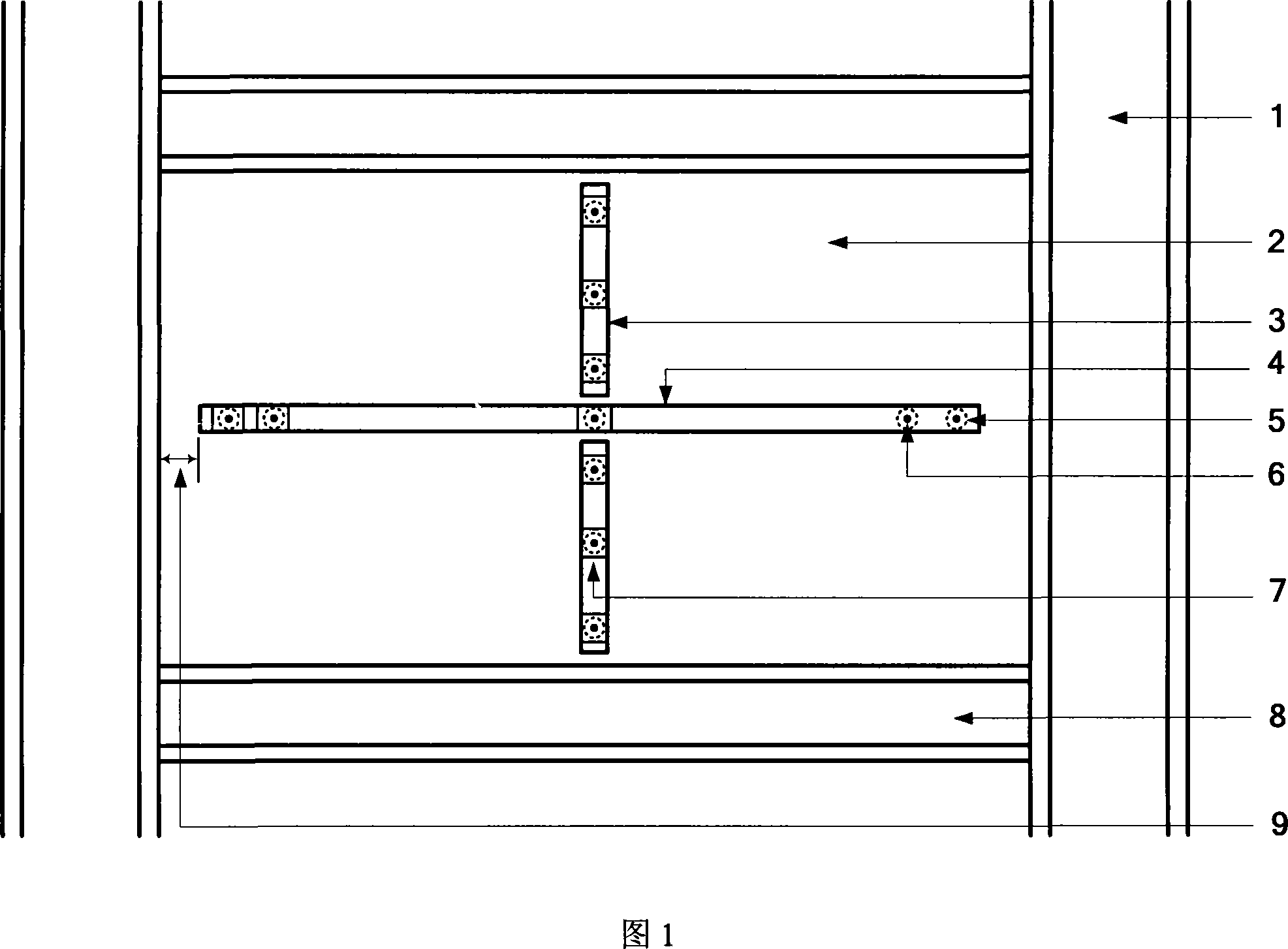
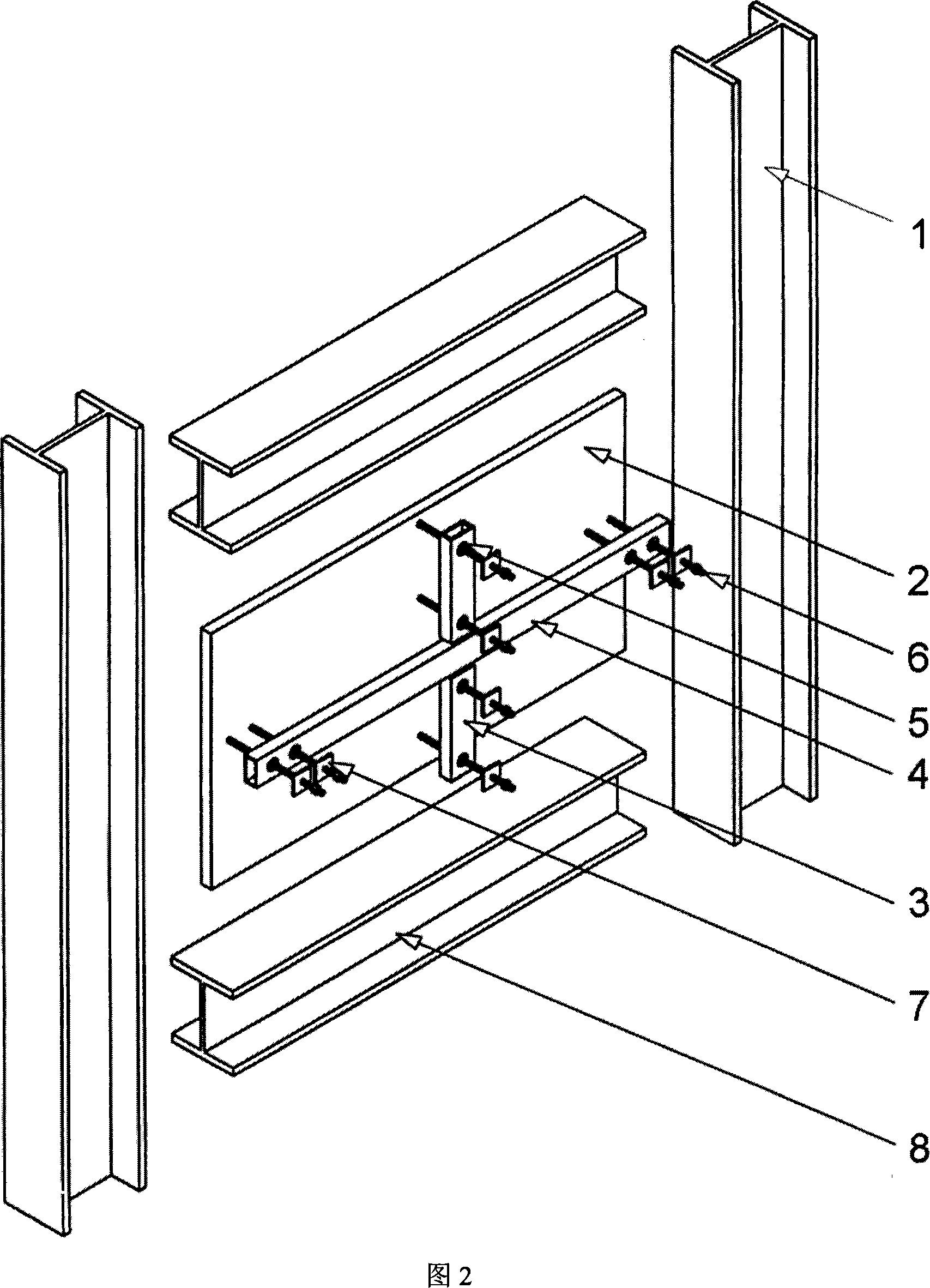
[0017] The technical scheme of the present invention is described in detail below in conjunction with accompanying drawing:

[0018] As shown in Figure 1-2:

[0019] 1- Edge frame post

[0020] 2- Embedded steel plate

[0021] 3- Vertical section steel stiffener

[0022] 4- Transverse section steel stiffener

[0023] 5- The large round hole reserved on the steel stiffener

[0024] 6-Connecting bolts between embedded steel plates and steel stiffeners

[0025] 7-Steel spacer between nut and steel stiffener

[0026] 8-edge frame beam

[0027] 9-Gap between edge member and steel stiffener

[0028] The non-bonded stiffened steel plate wall of the present invention is composed of embedded steel plates, steel plate front and rear section steel stiffeners and edge components; the edge components are composed of edge columns 1 and edge beams 8, and the embedded steel plates 2 are made of low yield point high ductility steel or high strength High ductility steel; the front and r...


PUM


Abstract

The invention relates to a cementation-free reinforced steel plate shear wall which belongs to the technical field of the constructional engineering and is characterized in that: the shear wall consists of an internally-embedded steel plate unit, a formed steel reinforcing rib unit and a boundary member, the boundary member consists of an edge pillar and an edge beam, the formed steel reinforcing rib adopts a cold bent thin-wall formed steel member that has the cross section of curl rim cap, box or other shapes; The internally-embedded steel plate and the formed steel reinforcing rib are connected by a passing bolt which can penetrate the internally-embedded steel plate and the formed steel reinforcing rib or a prestressed bolt; a large round hole is opened on the formed steel reinforcing rib so that the prestressed bolt can pass through and has enough sliding space; A certain clearance is kept between the internally-embedded steel plate unit, the formed steel reinforcing rib unit and the boundary member. The cementation-free reinforced steel plate shear wall provided by the invention is a novel member to resist the side force for the steel structure or other structure of the high-rise building, and is characterized by good earthquake-resistant performance, high ductility, plumb energy-saving hysteresis loop, easy construction and so on and is an excellent shock-resistant and energy-consuming member.

Description

technical field [0001] The invention relates to a novel lateral force-resistant, non-bonding stiffened steel plate shear wall, which belongs to the technical field of structural engineering. Background technique [0002] As a new type of lateral force-resisting member, thin-steel shear walls have been widely used in multi-story steel structures in the United States, Japan, and Canada, and have also emerged in low-rise residential steel structures in recent years. Because of its superior mechanical properties and good economy, thin steel plate shear walls have also begun to be used as lateral force-resistant members of high-rise steel structures in high-intensity earthquake-resistant fortification areas in my country. [0003] However, the thin steel plate shear wall exhibits two stress defects during the earthquake action. One is that the hysteresis curve has a serious pinching phenomenon, which is not conducive to the consumption of seismic energy. In the process of buckli...

Claims


Application Information

Patent Timeline
IPC IPC(8): E04B2/00E04B2/56E04B1/98
Inventor 郭彦林
Owner TSINGHUA UNIV
Learn More