Outer inflatable engine

An engine and air-inflated technology, which is applied in the direction of engine components, combustion engines, machines/engines, etc., can solve the problems of engine output power drop, mechanical loss, aerodynamic loss, reduction of intake air volume and waste in a single suction stroke, and achieve The effect of increasing power per liter, reducing emissions, and low cost

Inactive Publication Date: 2008-02-20
靳北彪
View PDF0 Cites 5 Cited by
  • Summary
  • Abstract
  • Description
  • Claims
  • Application Information

AI Technical Summary

Problems solved by technology

[0002] The output power of a traditional engine is determined by the cylinder volume and speed of the engine, and the increase in the cylinder volume will inevitably increase the volume and weight of the engine, and bring greater mechanical loss; and the increase in speed will inevitably bring huge The mechanical loss, aerodynamic loss and the reduction of the intake volume of a single intake stroke; in turn, the output power per unit revolution of the engine will decrease, and the efficiency of the engine will also decrease; Had to be equipped with a large engine, such an engine is not only large in size and weight, but also because the power required by the vehicle most of the time is far lower than the rated output power of the engine, so the engine works in the low efficiency area for a long time, resulting in a lot of waste

Method used


Image

  • Outer inflatable engine
  • Outer inflatable engine
  • Outer inflatable engine

Examples


Embodiment 1

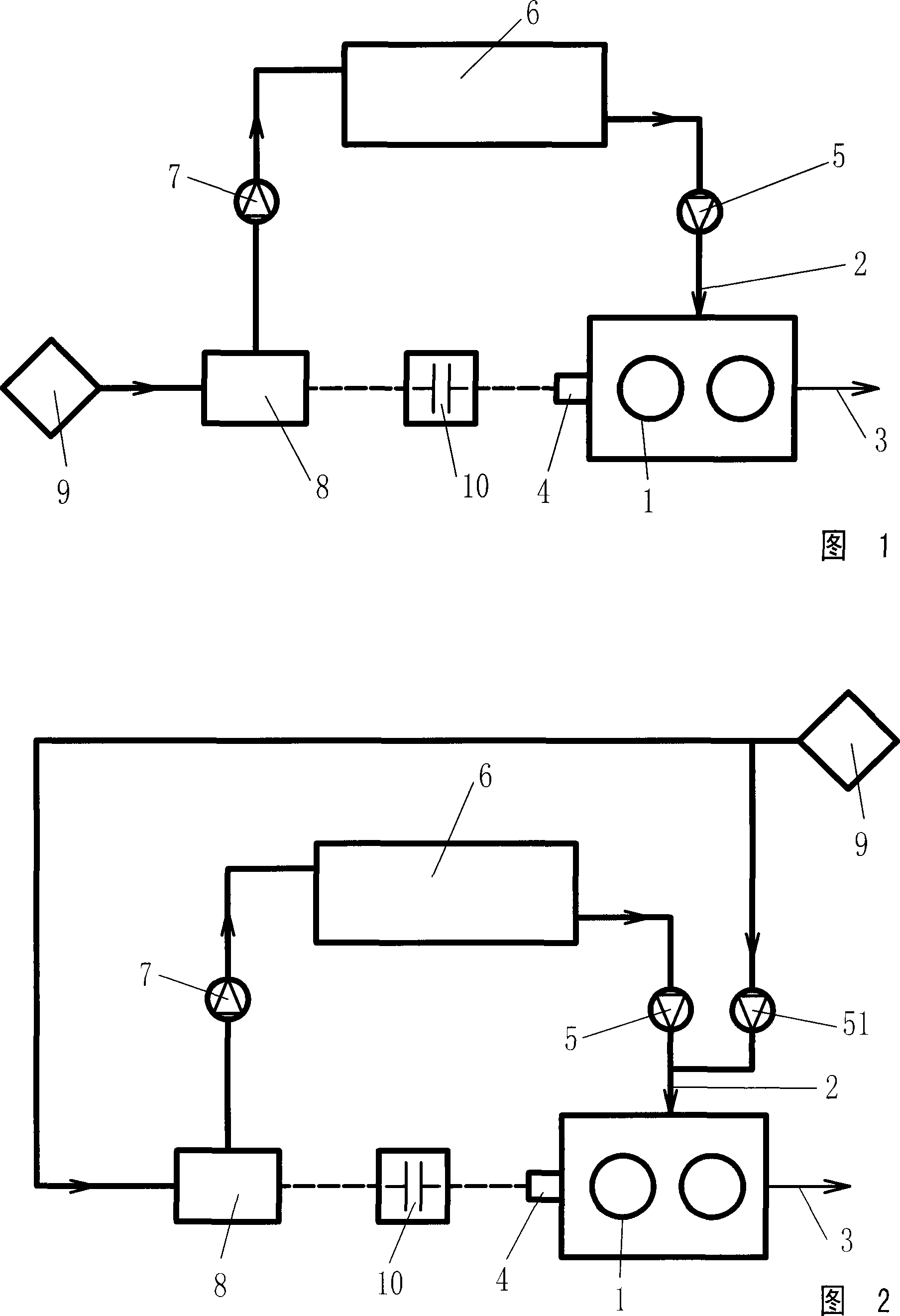
[0048] The externally charged engine as shown in Figure 1 includes a cylinder 1, an air inlet 2, an exhaust 3, and a crankshaft 4, and the air inlet of the cylinder 1 communicates with the outlet of the air storage tank 6 through the control device 5, and the The inlet of the air storage tank 6 is communicated with the compressed air outlet of the air compressor 8 through the control device 7, the air inlet of the air compressor 8 is communicated with the intake system 9, and the power input shaft of the air compressor 8 is directly or via The clutch 10 is connected with the crankshaft 4 of the engine, and the camshaft and the crankshaft of the engine are set at constant speeds, that is, within the range of 360 degrees of crankshaft rotation, the engine completes high-pressure charging, secondary compression, work and exhaust processes.

Embodiment 2

[0050] The externally charged engine shown in Figure 2 is different from Embodiment 1 in that a control device 51 connected in parallel with the control device 5 is provided at the air inlet of the cylinder 1, and the control device 51 is connected with the intake port. Gas system 9 communicates, and the rotating speed of the camshaft of described engine is set as 1 / 2 of crankshaft rotating speed, namely within the range of 720 degree of crankshaft rotation, engine completes suction charging stroke, compression stroke, power stroke and exhaust stroke.

Embodiment 3

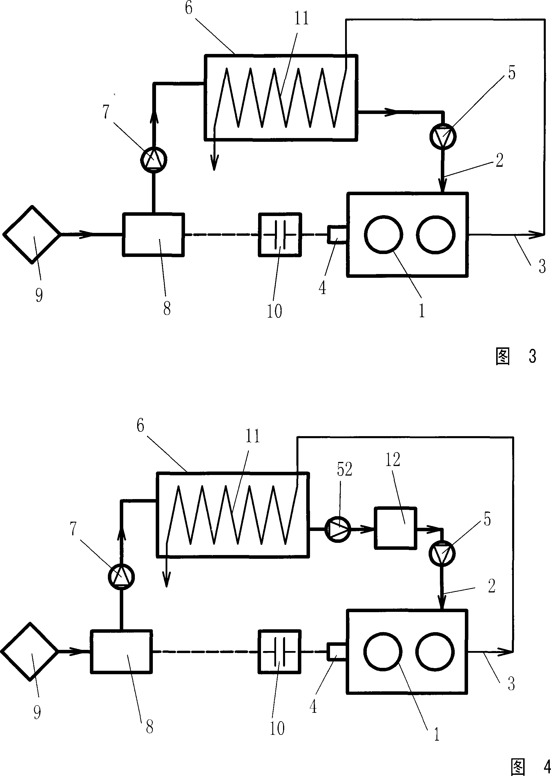
[0052] The difference between the externally charged engine shown in FIG. 3 and Embodiment 1 is that the exhaust passage 3 communicates with the heat exchanger 11 arranged in the air storage tank 6 .


PUM


Abstract

The invention relates to an outer inflatable type engine, which comprises an air cylinder, an inlet passage, an exhaust passage and a crankshaft; the inlet of the air cylinder is communicated with the outlet of an air reservoir through a controlling device, the inlet of the air reservoir is communicated with the compressed air outlet of an air compressor through a controlling device, the air inlet of an air compressor is communicated with an air intake system, the power input shaft of the air compressor is connected with the engine crankshaft directly or through a clutch, the rotation speed of the engine camshaft equals to that of the crankshaft, namely, the engine finishes the high-pressure charging, the secondary compression, the working process and the exhaust process when the crankshaft rotates for 360 degrees. The invention can adjust the air input of the engine in a wide range and thus can considerably improve the power-to-volume ratio, the thermal efficiency, the power regulation scope and considerably reduces the emission of harmful substances; the invention can improve the instant output power of the engine by double times and has simple structure, small volume, energy conservation, environment-protective and is suitable for any equipment with an engine.

Description

technical field [0001] The invention relates to the field of engines. Background technique [0002] The output power of a traditional engine is determined by the cylinder volume and speed of the engine, and the increase in the cylinder volume will inevitably increase the volume and weight of the engine, and bring greater mechanical loss; and the increase in speed will inevitably bring huge The mechanical loss, aerodynamic loss and the reduction of the intake volume of a single intake stroke; in turn, the output power per unit revolution of the engine will decrease, and the efficiency of the engine will also decrease; Have to equip large engine, such engine is not only bulky, and weight is heavy, and because the power needed by vehicle most of the time is far lower than the rated output power of engine, so engine works in low efficiency area for a long time, and the result causes very big waste. Due to the above-mentioned reasons, so far, the lift efficiency of the engine ha...

Claims


Application Information

Patent Timeline
Patent Type & Authority Applications(China)
IPC IPC(8): F02B33/44F01L1/344F02M31/08F02B33/00F02B23/00F02B29/00F02B61/00F02M25/12
CPCY02T10/146Y02T10/125Y02T10/121Y02T10/12
Inventor 靳北彪
Owner 靳北彪
Why Eureka
Try Eureka