
Highly precise speed mode control system for magnetic floating counteractive flywheel electromotor

A reaction flywheel, rate mode technology, applied in the field of aerospace control, can solve the problems of low speed control and low precision

Inactive Publication Date: 2008-02-20
BEIHANG UNIV
View PDF0 Cites 21 Cited by
  • Summary
  • Abstract
  • Description
  • Claims
  • Application Information

AI Technical Summary

Problems solved by technology

[0004] The technical problem solved by the present invention is: to overcome the deficiency of low-speed control precision of the existing maglev reaction flywheel, to provide a high-precision speed mode control system of the maglev reaction flywheel motor, which greatly improves the control resolution and precision of the maglev reaction flywheel

Method used


Image

  • Highly precise speed mode control system for magnetic floating counteractive flywheel electromotor

Examples


Embodiment Construction

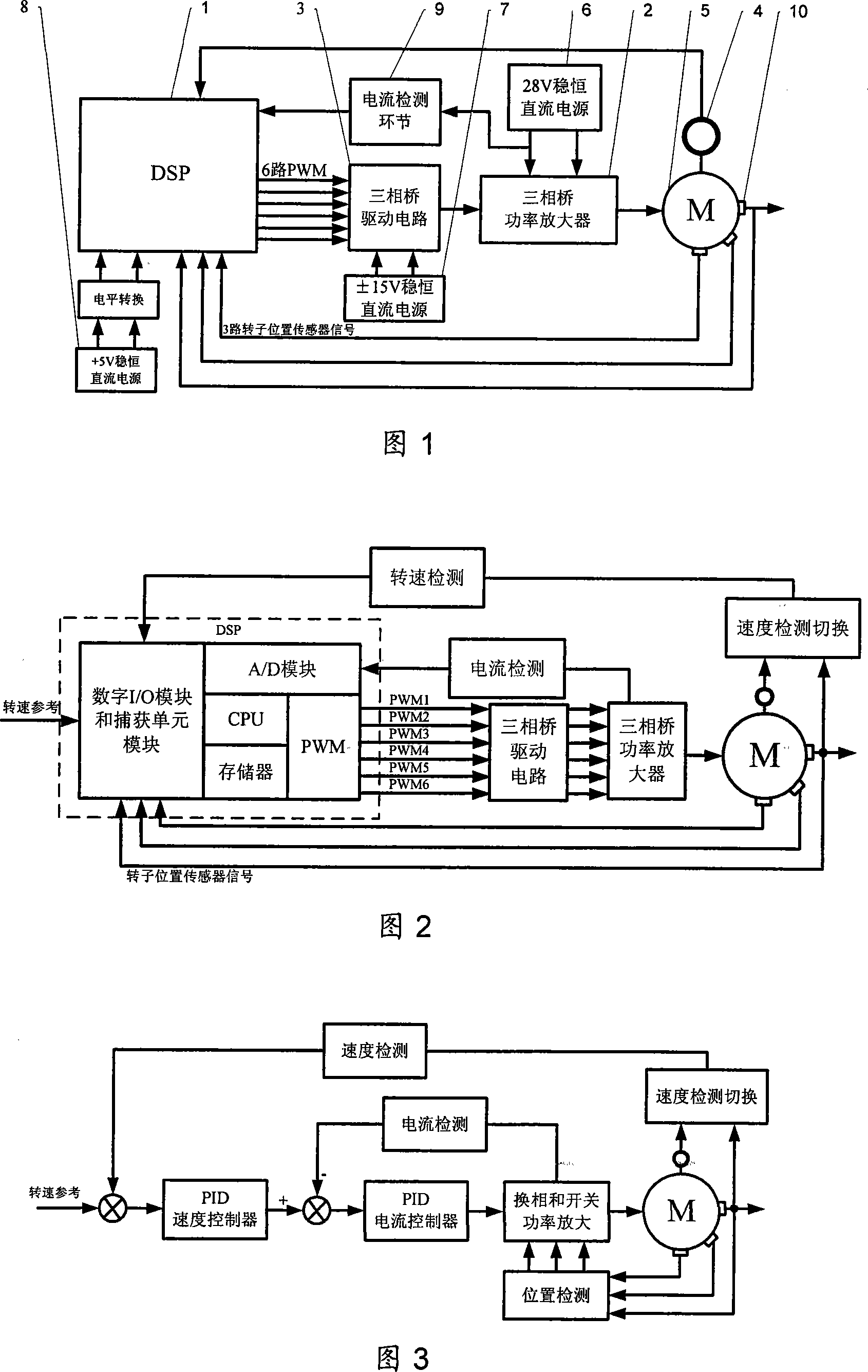
[0012] As shown in Fig. 1, the present invention is by DSP as the core controller 1, three-phase bridge power amplifier 2, three-phase bridge drive circuit 3, incremental shaft angle encoder 4, three-phase permanent magnet brushless DC motor 5, 28V direct current Constant power supply 6, ±15V DC constant power supply 7, +5V DC constant power supply 8, current detection link 9 and Hall effect rotor position sensor 10, when the three-phase permanent magnet brushless DC motor of the magnetic levitation reaction acts on the flywheel, the speed is 5 When the speed is low, the speed feedback signal is obtained from the incremental shaft angle encoder 4. When the speed reaches above the electrical allowable speed, the speed feedback signal is obtained from the Hall effect rotor position sensor 10, and the output signal of the Hall effect rotor position sensor 10 is obtained by The capture unit of controller 1 with DSP as the core captures and generates commutation logic. The output si...


PUM


Abstract

The utility model relates to a high precision velocity-mode control system of a magnetic levitation counteractive flywheel motor, which is used in a high precision attitude control executive device of a new-generation satellite with high-stability, namely the high precision velocity controlling of the magnetic levitation counteractive flywheel motor. The utility model mainly comprises a controller with a DSP as the core, a three-phase bridge power amplifier, a three-phase bridge drive circuit, an increment type shaft angle encoder, a three-phase permanent magnetic brushless direct current motor, a 28V steady direct current power supply, a +15V steady direct current power supply, a plus or minus 5V steady direct current power supply, a current checking part and Hall-effect rotor position sensor. Through the two channels of orthogonal encoding pulse signal of the increment type shaft angle encoder, the utility model provides the low-velocity controlling of the magnetic levitation counteractive flywheel motor with the velocity feedback when the velocity is in the electrically allowable rotational speed range of the increment type shaft angle encoder to realize the high precision velocity-mode controlling of the magnetic levitation counteractive flywheel motor; the signal of the Hall-effect rotor position sensor is used as the velocity feedback when the velocity is out of the electrically allowable rotational speed range of the increment type shaft angle encoder.

Description

technical field [0001] The invention relates to a high-precision rate mode control system of a magnetic levitation reaction flywheel motor, which belongs to the field of aerospace control and is used to realize attitude control of a new generation of high-precision and high-stability satellites. Background technique [0002] The new generation of satellite earth observation technology is becoming more and more perfect. It is a multi-layer, three-dimensional, multi-angle, all-round and all-weather, high, medium and low orbit combination, large, medium and small satellite coordination, coarse, fine and fine resolution Complementary global Earth observation systems are being formed. The high-precision and high-stability attitude control technology of the new generation of earth observation satellites is one of the key technologies that need a breakthrough. [0003] The reaction flywheel is widely used as the executive part of satellite attitude control, and its average angular...

Claims


Application Information

Patent Timeline
Patent Type & Authority Applications(China)
IPC IPC(8): H02P6/06G05D1/00
Inventor 房建成王志强刘刚樊亚洪
Owner BEIHANG UNIV
Learn More