Water-cooling middle case turbocharging mechanism

A turbocharging and turbine impeller technology, applied in liquid cooling, mechanical equipment, engine components, etc., can solve problems such as functional aging and poor cooling of engine superchargers, so as to promote power, improve cooling effect, and maintain structural changes Effect

Inactive Publication Date: 2008-02-27
奚友秋
View PDF0 Cites 23 Cited by
  • Summary
  • Abstract
  • Description
  • Claims
  • Application Information

AI Technical Summary

Problems solved by technology

By setting the supercharger cooling channel, water is used to cool the supercharger middle shell, turbine and lubricating oil passing through the supercharger, so as to ensure that the supercharger is fully cooled and maintains a good working condition, thereby solving the problem of the engine supercharger. Defects of poor cooling and functional aging of engine lubricating oil after heat absorption by the supercharger

Method used


Image

  • Water-cooling middle case turbocharging mechanism

Examples


Embodiment Construction

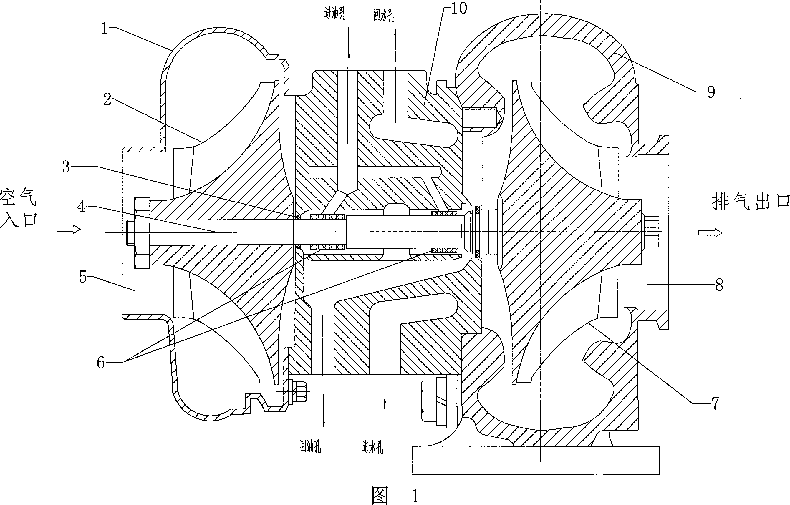
[0011] As shown in the figure: the compressor impeller 2 and the turbine impeller 7 are installed on the supercharger shaft 4, and it is characterized in that: there is a water-cooled intermediate shell 10 between the compressor impeller 2 and the turbine impeller 7, and on the water-cooled intermediate shell 10 A water inlet hole and a water return hole are provided, and the water inlet hole and the water return hole are communicated with each other by means of a passage arranged in the water-cooled middle shell 10, and cooling water enters the passage in the water-cooled middle casing 10 through the water inlet hole, and the water-cooled middle casing 10 After cooling, it is discharged from the return hole; there is a compressor pressure shell 1 outside the compressor impeller 2, and a turbine volute 9 outside the turbine impeller 2.

[0012] A floating bearing 6 is provided at the junction of the supercharger shaft 4 and the water-cooled middle case 10, and an oil inlet hole...


PUM


Abstract

The present invention relates to technology of increasing the air density and the air intake amount of turbo supercharging mechanism, and is especially one kind of water cooled intermediate shell turbo supercharging mechanism. The technological scheme is that one water cooled intermediate shell with mutually communicated water inlet hole and water returning hole is set between the air compressor vane wheel and turbine vane wheel on supercharger shaft, and water is made to enter into the water cooling passage inside the intermediate shell for heat exchange circulation. The present invention can increase the air density and the air intake amount to ensure complete combustion in the combustor of engine, increase engine power and reduce tail gas exhaust.

Description

technical field [0001] The invention relates to a technology for increasing the air density of a turbocharger mechanism and increasing the intake air volume, in particular to a water-cooled middle casing turbocharger mechanism. Due to the increase of intake air density, the intake air volume can be increased correspondingly, so that the combustion chamber of the engine can be burned more fully, so that the engine power can be increased and the emission of automobile exhaust can be reduced. Background technique [0002] In order to fully burn the fuel and reduce the discharge of exhaust pollutants in the existing multi-cylinder engines, methods such as improving the fuel system of the diesel engine such as the electronic control fuel injection system and the structure of the combustion chamber are generally adopted, but this will inevitably increase the cost of the engine. Customers bring too much economic expenditure; ordinary turbochargers only rely on air cooling for super...

Claims


Application Information

Patent Timeline
Patent Type & Authority Applications(China)
IPC IPC(8): F01P3/12F02B39/00
Inventor 奚友秋
Owner 奚友秋
Why Eureka
Try Eureka