Non-dispersive whole-static method for non-fluorescent object spectral measurement

A technology of spectral measurement and static method, which is applied in the field of non-spectroscopy and full static of non-fluorescent object spectral measurement, and can solve the problems of complex optical path structure, large volume, high environmental requirements, etc.

Inactive Publication Date: 2008-02-27
HENAN UNIVERSITY OF TECHNOLOGY
View PDF0 Cites 2 Cited by
  • Summary
  • Abstract
  • Description
  • Claims
  • Application Information

AI Technical Summary

Problems solved by technology

[0007] The purpose of the present invention is to solve the problems of complex optical path structure, bulky volume and high environmental requirements in the existing spectral measurement methods, so as to provide a non-fluorescent object spectral measurement method with simple structure, small size and low environmental requirements. spectroscopic all-static method

Method used


Image

  • Non-dispersive whole-static method for non-fluorescent object spectral measurement
  • Non-dispersive whole-static method for non-fluorescent object spectral measurement
  • Non-dispersive whole-static method for non-fluorescent object spectral measurement

Examples


Embodiment 1

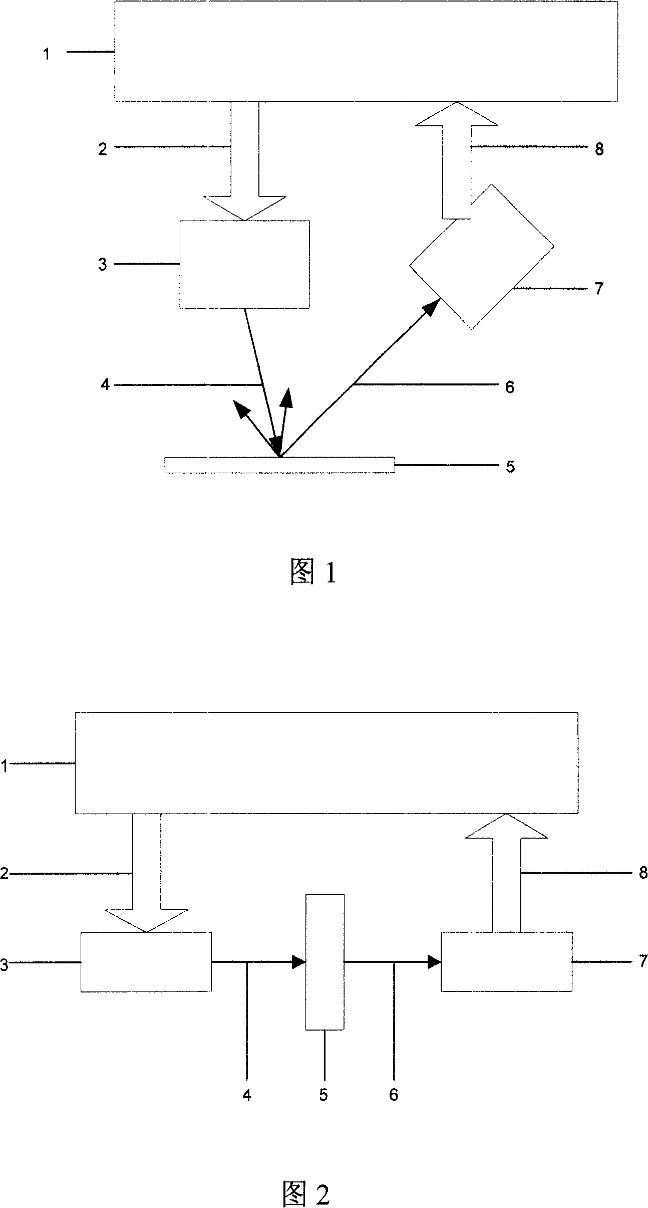
[0043] As shown in the figure, the measurement method of the present invention is as follows:

[0044] For the measurement of reflectance spectra:

[0045] If it is necessary to measure N wavelength ranges in a certain band (λ n , n=1,2,3,..., the spectral reflectance factor of N), concrete method is:

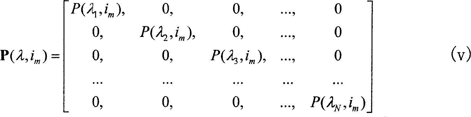
[0046] The first step: select the illumination and observation conditions of the reflective sample, and determine the control variable i of the illuminator (3) m The spectral power distribution P(λ,i in this band under control m ), P(λ, i m ) is the lighting body when the control variable is i m The spectral power distribution matrix when

[0047] P ( λ , i m ) = P ( λ 1 , ...

Embodiment 2

[0074] Measurement method of the present invention is as follows:

[0075] For the measurement of reflectance spectra:

[0076] If it is necessary to measure N wavelength ranges in a certain band (λ n , n=1,2,3,..., the spectral reflectance factor of N), concrete method is:

[0077] The first step: select the illumination and observation conditions of the reflective sample, and determine the control variable i of the illuminator (3) m The spectral power distribution P(λ,i in this band under control m ), P(λ, i m ) is the lighting body when the control variable is i m The spectral power distribution matrix when

[0078] P ( λ , i m ) = P ( λ 1 , ...

Embodiment 3

[0104] Measurement method of the present invention is as follows:

[0105] For the measurement of reflectance spectra:

[0106] If it is necessary to measure N wavelength ranges in a certain band (λ n , n=1,2,3,..., the spectral reflectance factor of N), concrete method is:

[0107] The first step: select the illumination and observation conditions of the reflective sample, and determine the control variable i of the illuminator (3) m The spectral power distribution P(λ,i in this band under control m ), P(λ, i m ) is the lighting body when the control variable is i m The spectral power distribution matrix when

[0108] P ( λ , i m ) = P ( λ 1 , ...


PUM


Abstract

The invention discloses a non-spectroscopical static spectral measurement method of non-fluorescence objects, the method adopt computer or microprocessor controlled variable spectral power distribution light as a test lighting source, when the photoelectric sensor work in the linear range, through solving linear equation group to calculate the spectral reflectance factor, spectral transmission ratio or absorption spectrum of objects. This method do not need prism, grating, interferometer, filters, optical fiber components to split light, the detection device is small in size, can obtain high test accuracy and speed. The method of the invention does not have mobilizable mechanical parts, all static; reduces weight and power consumption of the system, thereby it is simple in structure, with low cost, has high reliability and engineering application feasibility.

Description

technical field [0001] The invention relates to a method for measuring the spectrum of an object, in particular to a non-spectroscopic all-static method for measuring the spectrum of a non-fluorescent object. Background technique [0002] In many fields such as modern industry, agriculture, trade, medicine, scientific research and daily life, there are a large number of object spectrum measurement problems. For example, in the visible light band, measuring the reflection and transmission spectrum of an object can accurately calculate the color of the object; in the infrared wavelength range, using absorption spectroscopy can qualitatively or quantitatively analyze the organic or inorganic components of the object. [0003] Spectral measurement requires spectral separation using wavelength separation techniques. Existing spectroscopic techniques all require the use of certain optical components, such as prisms, gratings, interferometers, optical filters, optical fibers, and ...

Claims


Application Information

Patent Timeline
Patent Type & Authority Applications(China)
IPC IPC(8): G01N21/25G06F19/00
Inventor 杨红卫周展明
Owner HENAN UNIVERSITY OF TECHNOLOGY
Why Eureka
Try Eureka