EMI-reducing single-stage power factor correcting circuit

A power factor correction, circuit technology, applied in the output power conversion device, the conversion of DC power input to DC power output, electrical components and other directions, can solve the problems of large harmonic distortion, complex structure, etc., to simplify the structure and improve EMI. , to achieve the effect of power factor correction

Inactive Publication Date: 2008-03-05
ZHEJIANG UNIV
View PDF2 Cites 9 Cited by
  • Summary
  • Abstract
  • Description
  • Claims
  • Application Information

AI Technical Summary

Problems solved by technology

However, on the AC input side, there are a total of six diodes, the structure is complex, and the bypass d...

Method used


Image

  • EMI-reducing single-stage power factor correcting circuit
  • EMI-reducing single-stage power factor correcting circuit
  • EMI-reducing single-stage power factor correcting circuit

Examples


Embodiment Construction

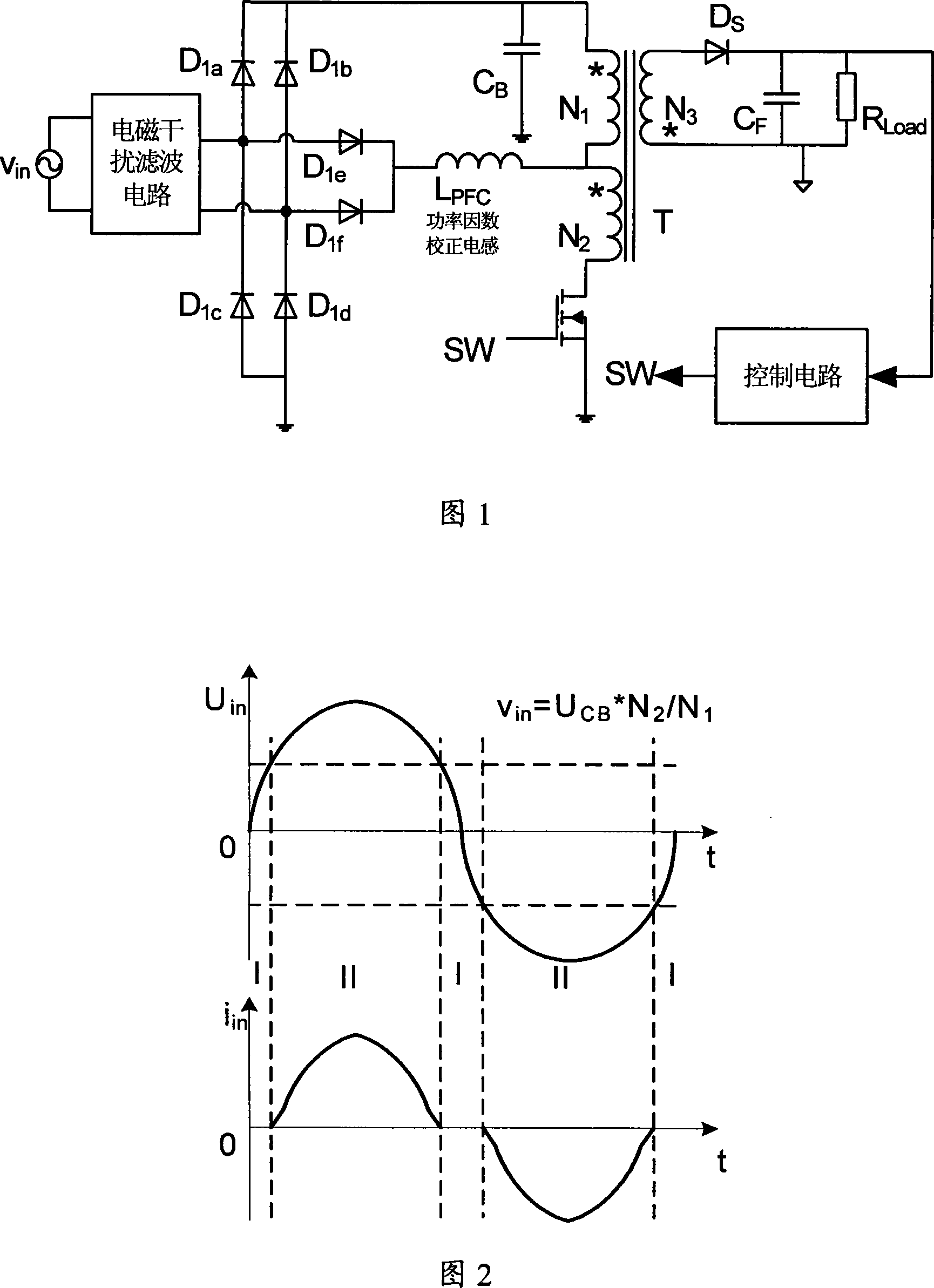
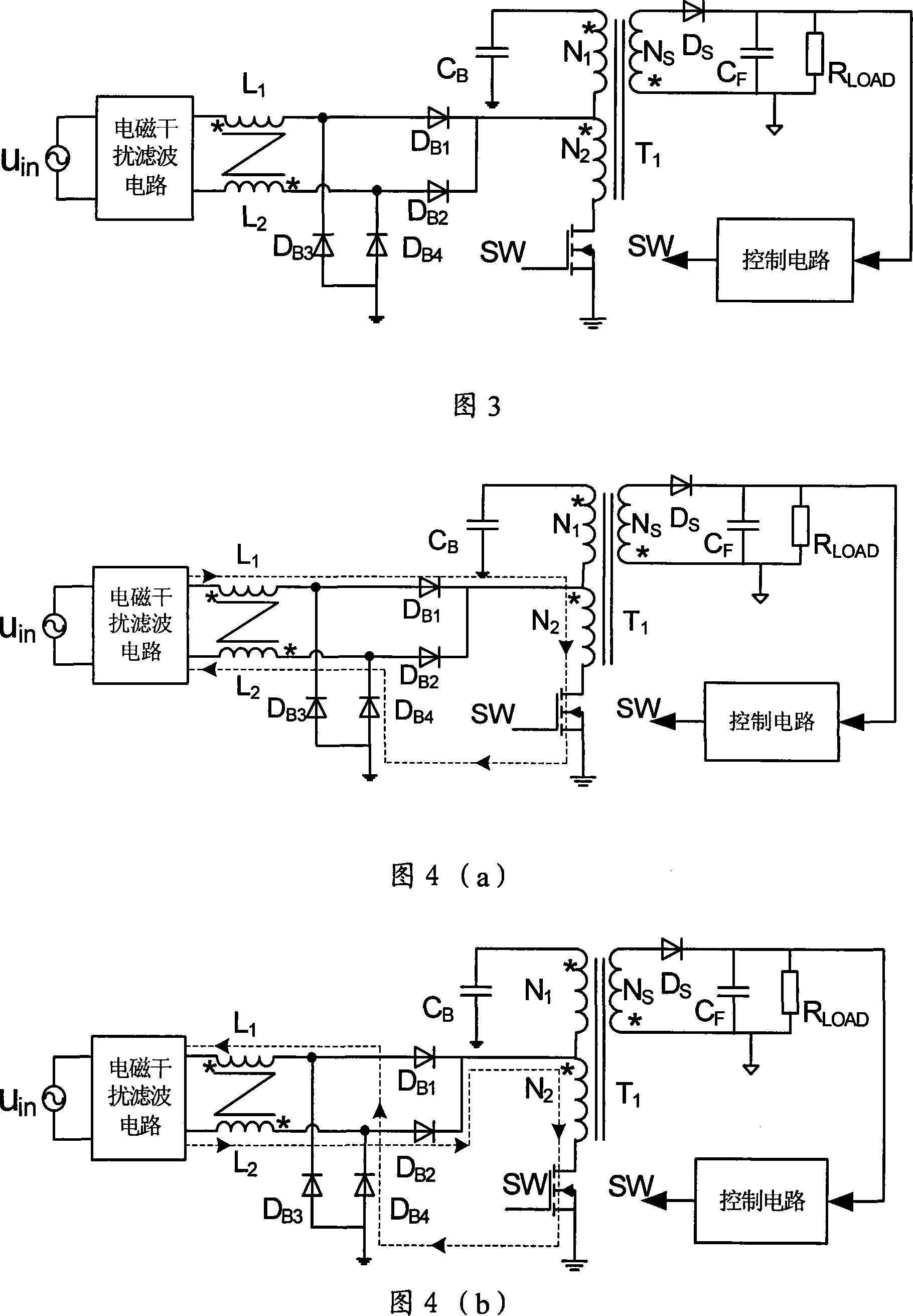
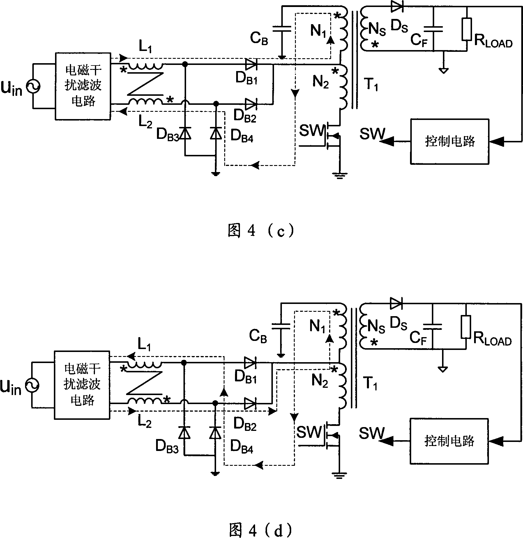
[0029] Based on the circuit shown in Figure 1, a PFC inductor L coupled with two windings is used 1 , L 2 , and place it before the rectifier bridge, the single-stage power factor correction circuit of the present invention shown in Fig. 3 is obtained, wherein the two bypass diodes D in Fig. 1 are canceled 1a 、D 1b. This circuit retains the advantages and achievements of the circuit in Figure 1. The structure of the primary winding tap can feed back the energy storage capacitor voltage to make it lower than 400V; when the switch tube SW is turned on or off, in the formed power loop, There are only two diode voltage drops, and the conduction loss is low; when the switch tube SW is turned off, the PFC inductance L 1 , L 2 Part of the stored energy is charged to the energy storage capacitor, and the other part is directly transmitted to the secondary side through the transformer to improve the overall efficiency. The control circuit controls the turn-on and turn-off of the s...


PUM


Abstract

This invention discloses a single-step power factor correction circuit for reducing EMI, which applies a mode of mutual couple of two windings and puts an inductor for correcting input current wave on the front of a rectifying bridge to improve the magnetic interference of single-step PFC circuit and limits voltage of energy-storing capacitor by connecting central taps of first windings of a transformer, when a switch tube is turned off, part of energy stored in the primary coupled PFC inductor is provided to the energy-stored capacitor for charging and the other is transmitted to the secondary by the transformer directly so as to increase the entire efficiency of the converter.

Description

technical field [0001] The invention relates to a power factor correction circuit, specifically a single-stage power factor correction circuit that adopts a coupled power factor correction (PFC) inductor and can reduce electromagnetic interference (EMI). Background technique [0002] The power factor correction circuit widely used at present is often the traditional two-stage power factor correction technology, but its circuit components are many, the cost is high, and the circuit is complicated, so it is not suitable for small and medium power applications. In order to reduce the cost of the two-stage power factor correction circuit, various single-stage power factor correction techniques have been proposed in recent years. A general single-stage power factor correction circuit automatically realizes the power factor correction function by controlling the inductor current to work in a discontinuous conduction mode. In order to achieve the balance of input and output power ...

Claims


Application Information

Patent Timeline
IPC IPC(8): H02M1/42H02M3/335
CPCY02B70/126Y02B70/10Y02P80/10
Inventor 马皓徐晔
Owner ZHEJIANG UNIV
Why Eureka
Try Eureka