Pulsing signal recognition device and method

A technology of pulse signal and identification device, which is applied in the direction of measuring device, pulse processing, pulse technology, etc., can solve the problems of absolute change of pulse height, inability to adapt to high-speed pulse signal, and impossibility of realization, so as to eliminate small disturbance and save storage Space and time-saving effects

Active Publication Date: 2008-03-05
SHENZHEN MINDRAY BIO MEDICAL ELECTRONICS CO LTD +1
View PDF0 Cites 17 Cited by
  • Summary
  • Abstract
  • Description
  • Claims
  • Application Information

AI Technical Summary

Problems solved by technology

① Signals that cannot adapt to baseline fluctuations
If the baseline fluctuates, it is possible to treat the floating baseline as a pulse, causing errors; on the other hand, the pulse is superimposed on the baseline, if the actual value of the pulse height does not change, but the baseline fluctuates, then the absolute value of the pulse height will also change
While the existing technology cannot adapt to this situation, it cannot extract the relative pulse height
The way to make up for this defect in the existing technology is usually to lower the threshold and store the baseline to participate in the analysis and identification, but the data volume of the baseline far exceeds the pulse, which makes the storage space increase sharply, and the time overhead for analysis and identification is also quite large. become too expensive to achieve
②It cannot adapt to high-speed pulse signals. When the sampling rate increases, the amount of data increases greatly, the requirements for storage space become large, and the processing time is also very large, and the real-time performance becomes poor.

Method used


Image

  • Pulsing signal recognition device and method
  • Pulsing signal recognition device and method
  • Pulsing signal recognition device and method

Examples


specific Embodiment 1

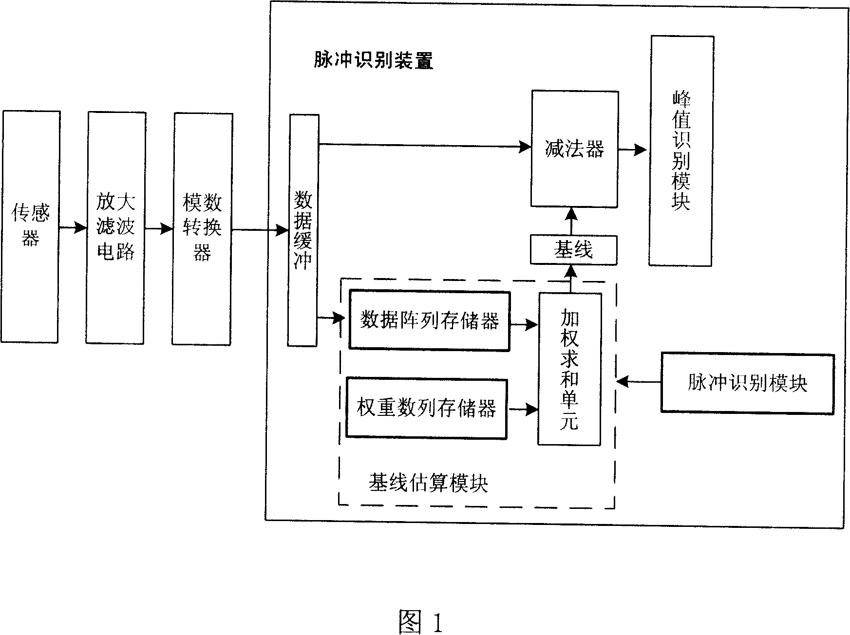
[0031] Specific Embodiment 1. As shown in FIG. 1 , the pulse signal identification device includes a baseline estimation module, a subtractor, a pulse identification module, and a peak identification module. The baseline estimation module receives the data during the non-duration period of the pulse, forms a data array, calculates the baseline value of the current pulse according to the data array, and the subtractor receives the pulse data and the baseline value, subtracts the baseline value from the pulse data to obtain the relative pulse data, that is Relative height, and output the relative pulse data to the peak identification module for pulse peak identification; the pulse identification module determines whether the difference exceeds or is lower than the predetermined first threshold according to the difference between the data point and the baseline, and determines the value of a pulse Start or end, and output the pulse continuation mark, pulse start mark and pulse end...

specific Embodiment 2

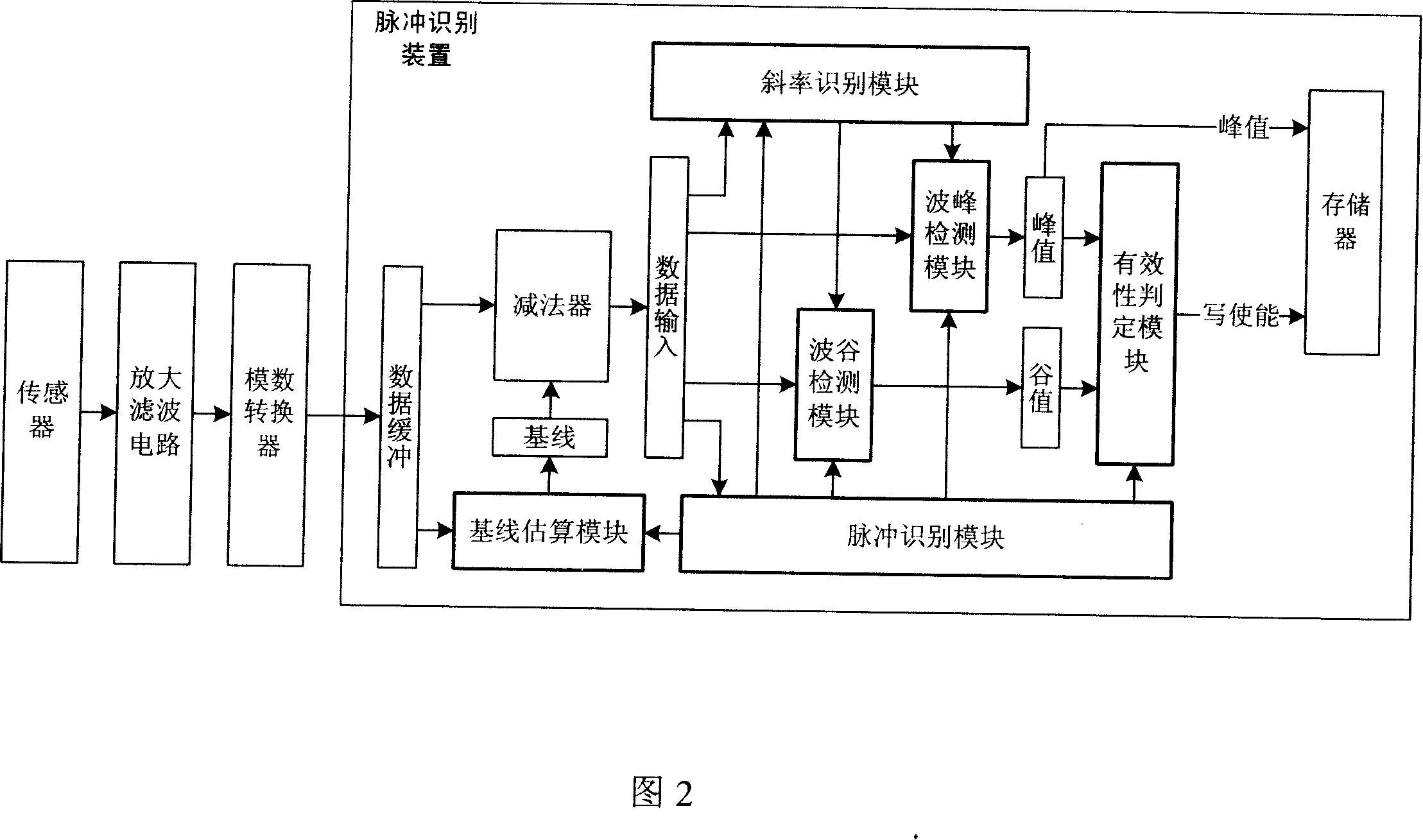
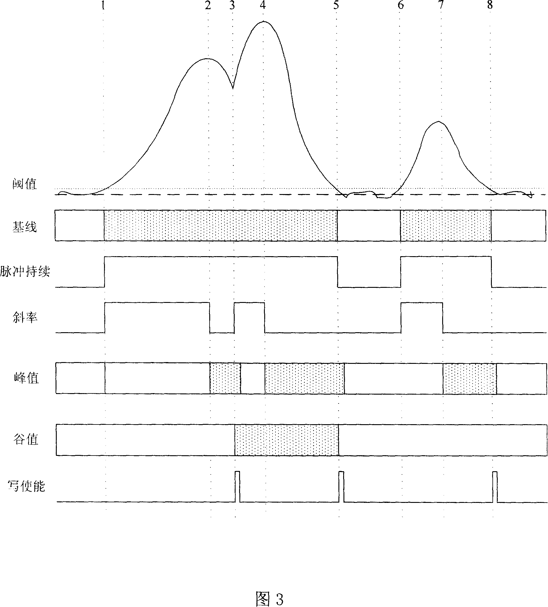
[0040] Embodiment 2. During the duration of the pulse, noise may cause a slight disturbance of the signal, which may affect the detection of the peak. This embodiment improves the peak identification module on the basis of Embodiment 1. As shown in Figure 2, the peak identification module includes a slope identification module and a peak detection module. The slope identification module responds to the output of the pulse identification module, receives relative pulse data during the pulse duration, and subtracts the data of the two sampling points before and after to calculate its slope. , when the absolute value of the slope (that is, the difference) exceeds the predetermined second threshold, it is considered to be a noise disturbance, and when the absolute value of the slope is within the predetermined second threshold range, it is considered to be an effective fluctuation, and the fluctuation flag is output . And when the slope changes from positive to negative, it indica...


PUM


Abstract

This invention discloses an identifying device for pulse signals including a base line calculation module, a subtracter and a peak value identifying module, in which, said base line calculation module receives data of pulses during a discontinuous period to form a data array and compute base line value according to the data array, said subtracter receives pulse data and the base line value and detracts the base line value with the pulse data to get related pulse data to be output to the identifying module, which can identify data directly not necessary to store data based on the parallel process to digital logic circuit and carries out identification to input pulse signals according to the identifying rule and output peak values meeting the rule in all the pulses in a stipulated time period and gives the corresponding writing enable signals of the peak value data used in storing operation.

Description

【Technical field】 [0001] The invention relates to a particle measurement system, in particular to a pulse signal identification device and method used in the particle measurement system to identify particles according to the peak value of the pulse signal. 【Background technique】 [0002] In the particle measurement system, when the measured particle passes, the sensor will generate a corresponding analog pulse signal, which is amplified and filtered, and then converted into a digital pulse signal, called pulse data. Then the application analyzes the pulse data. First, a threshold is set for the pulse data. The signal below the threshold is discarded, and the pulse data above the threshold is stored. Then, the pulse data is extracted from the beginning, and analyzed and identified according to the predetermined judgment criteria. Identify all pulse peaks in the pulse data. Then according to the proportional relationship between the pulse peak value and the volume of the part...

Claims


Application Information

Patent Timeline
Patent Type & Authority Applications(China)
IPC IPC(8): H03K5/1532G01T1/00
Inventor 郑俭锋易晗平代勇
Owner SHENZHEN MINDRAY BIO MEDICAL ELECTRONICS CO LTD
Why Eureka
Try Eureka