Modular building component and on-site hoisting building method

A building and assembly technology, applied in building construction, construction, etc., can solve the problems of time-consuming and laborious labor intensity, difficult quality control, lag in production process, etc., and achieve the effect of saving labor, simple structure, and easy on-site construction.

Inactive Publication Date: 2008-03-12
张兴汉
View PDF0 Cites 23 Cited by
  • Summary
  • Abstract
  • Description
  • Claims
  • Application Information

AI Technical Summary

Problems solved by technology

[0003] The purpose of the present invention is to overcome the disadvantages of lagging traditional production technology and unreasonable structure in the above background technology, resulting in time-consuming, labor-intensive, low work efficiency, and difficult qu

Method used


Image

  • Modular building component and on-site hoisting building method
  • Modular building component and on-site hoisting building method
  • Modular building component and on-site hoisting building method

Examples


Embodiment Construction

[0024] Below in conjunction with accompanying drawing and embodiment the present invention is further described:

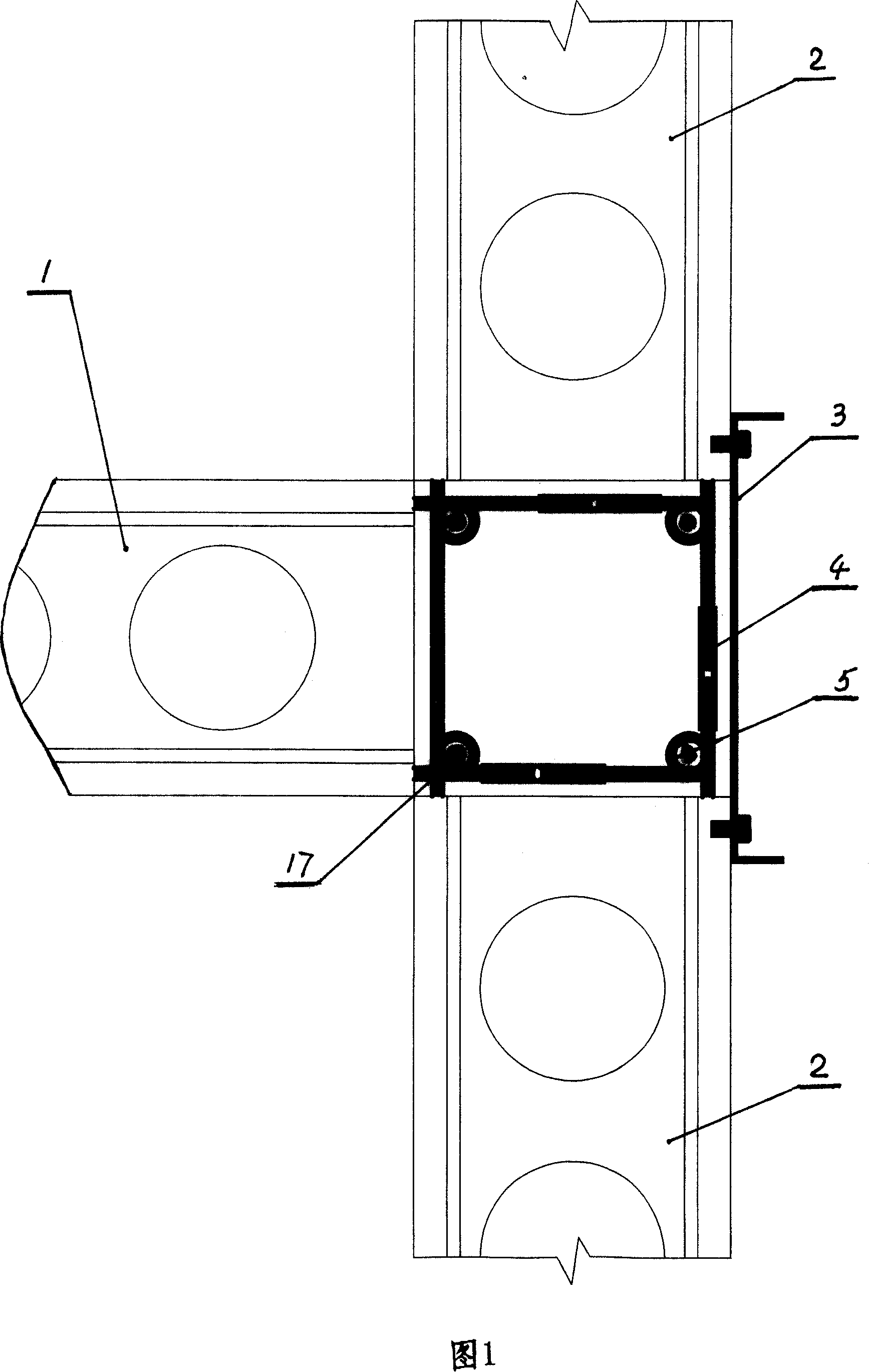
[0025] Referring to Figure 1, at the site, looking at the connection structure of the three wall panels from top to bottom, there are ring beam grooves on the three wall panels, and a square column at the connection of the three wall panels, and the belts fixed by the wall panels ( The stirrup bars 5 around the rings are connected as a whole through the horizontal position of the connecting sleeve 4, and the vertical ribs 17 of the structural columns are inserted in the rings of the upper and lower corresponding stirrup bars 5, and the formwork 3 is fixed outside the outer wall panel 2. Concrete 11 and stirrup bars 5 are added to form a connecting structural column with pouring and stamping, so that three boards are connected together to form a whole.

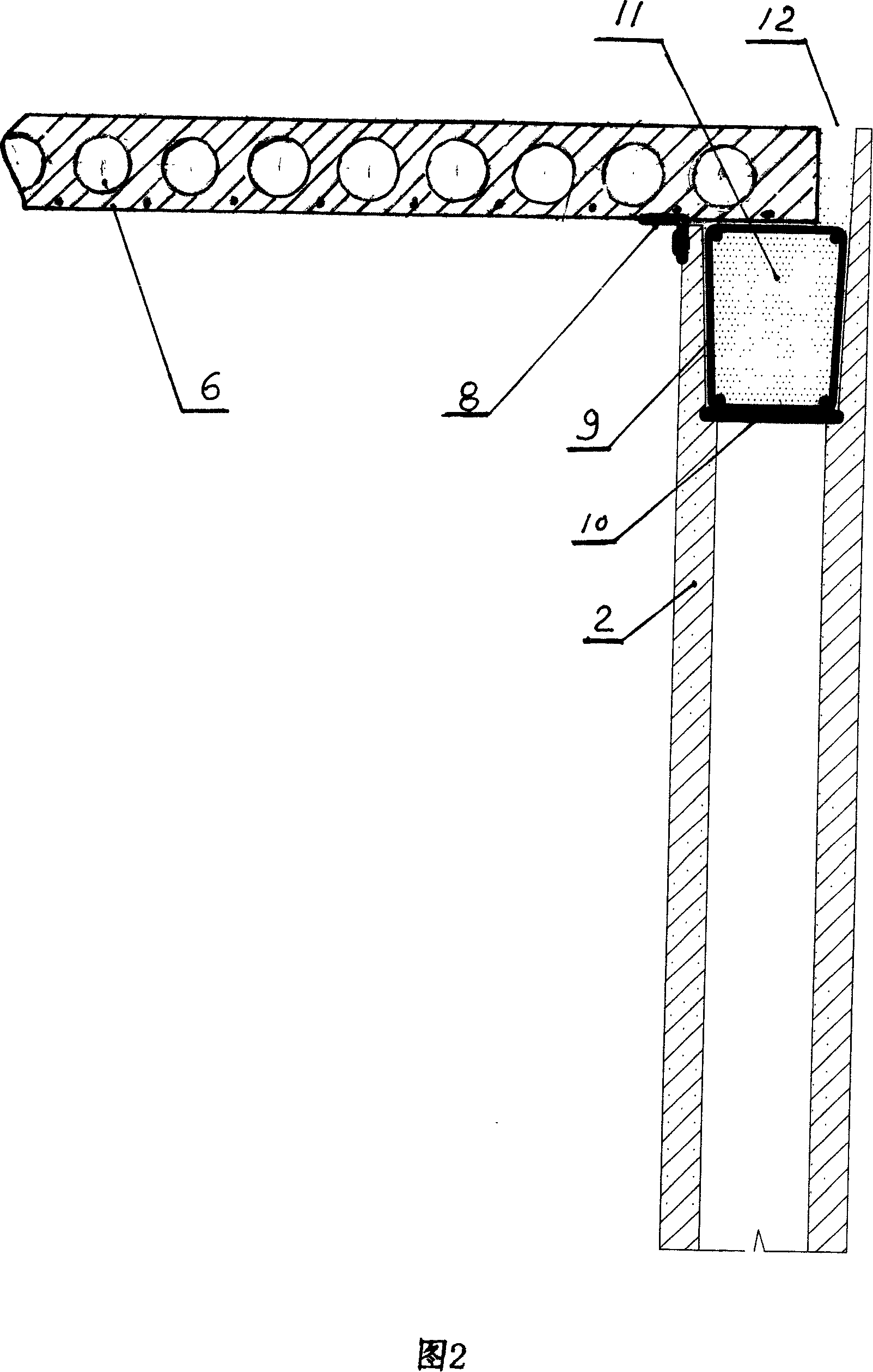
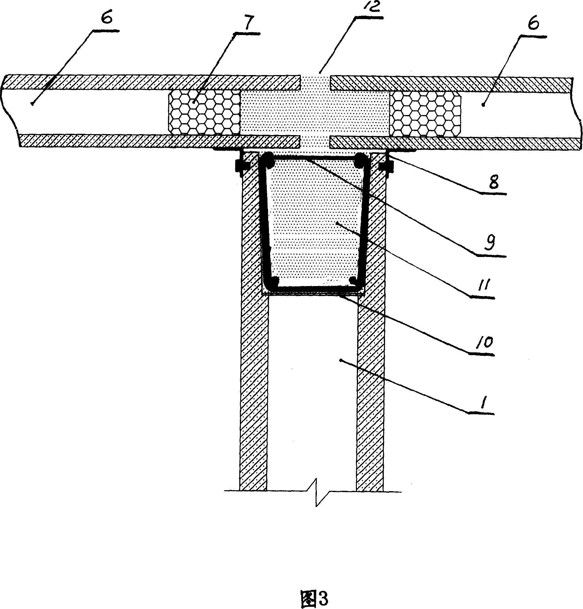
[0026] Referring to Fig. 2, it is the connection structure between the outer wall panel 2 and the floor slab 6, ...


PUM


Abstract

The invention relates to the fields of building materials and architectural technologies, in specific to a composite building member and an architectural method for field craning of cast-in-site beams and columns. At present, most of buildings in our country still follow the prior arts of manual masonry and painting for wall bodies, so that such problems as wasting time, wasting labor force and high labor intensity and etc are caused. The target of the invention is to fabricate all kinds of building members through industrialized production, and then, to transport to the construction site for craning and assembly. The technical scheme is as follows: Wall panels are supported through adjusting bracing rod assembly; partition wall panels and external wall panels are embedded with hooked nuts on side walls; the hooked nuts are connected with externally-arranged hoops; studs for fixed construction columns are put through upper rings and lower rings of the hoops, so that structural column bodies can be formed through pea gravel concrete casting and ramming. The invention has the following effects: Precast integrated large wall bodies, slabs and etc., so that no joggle seam appears on the panels after assembly, and neither face needs screeding or painting; meanwhile, the invention has advantages of safe, convenient, fast and smooth on-site execution, saving large number of form panels and scaffoldings, simple and convenient process, high integrated strength and perfect shockproof performances.

Description

1. Technical field [0001] The invention relates to the technical field of building materials and construction industrial production, and specifically refers to a construction method for industrially producing building components and transporting the components to the site for hoisting. 2. Background technology [0002] At present, in the field of construction in our country, most of them still follow the traditional wall that is manually built by a bricklayer and a knife, and then plastered by a plasterer. There is a problem of high labor intensity, low work efficiency and difficult quality control issues. On March 9, 2005, the State Intellectual Property Office announced the patent of "Small Quick-install Light Steel Structure Building Components" with application number 200420041516 and announcement number 2683744. It consists of connecting plates, steel columns, steel beams, and purlins. Its characteristics are: steel columns, steel beams, and purlins are rolled H-shaped...

Claims


Application Information

Patent Timeline
IPC IPC(8): E04B1/00E04B1/38
Inventor 张兴汉
Owner 张兴汉
Why Eureka
Try Eureka