High gain transmissive viewing screen

A high-gain, screen technology, applied in the field of transmissive screens and video rear-projection screens, can solve the problems affecting the viewing effect of screen images, and achieve the effect of high gain and large viewing angle

Inactive Publication Date: 2008-03-12
BEIJING FANGRUI BOSHI DIGITAL TECH
View PDF0 Cites 20 Cited by
  • Summary
  • Abstract
  • Description
  • Claims
  • Application Information

AI Technical Summary

Problems solved by technology

The diffuse transmissive screen cannot convert the light emitted by the projector on the screen into parallel light, and will form a spot effect centered on the straight line of the viewing angle that can be seen from all angles, affecting the viewing effect of the screen image

Method used


Image

  • High gain transmissive viewing screen
  • High gain transmissive viewing screen

Examples


Embodiment 1

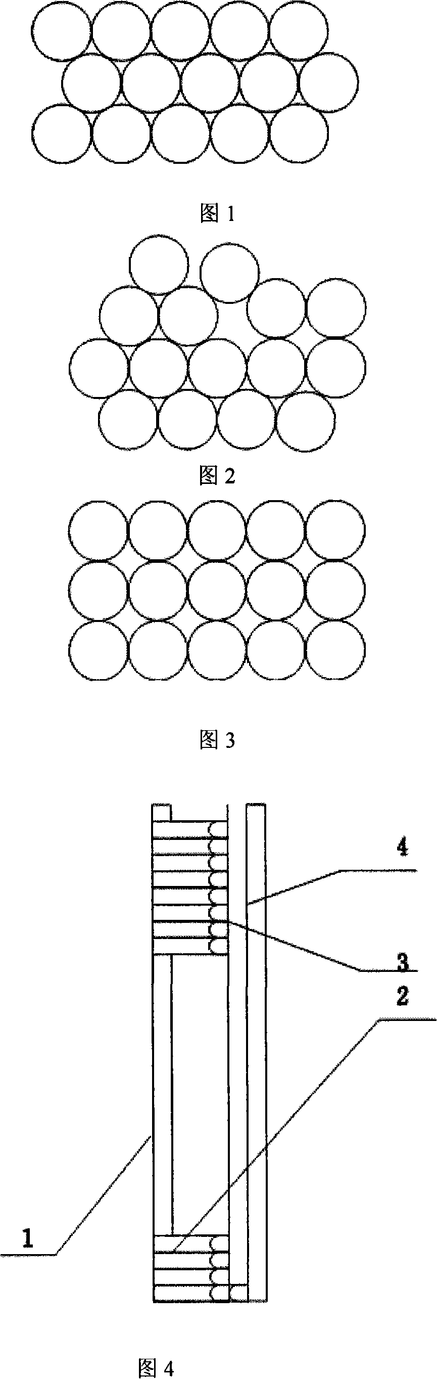
[0022] Example 1: Arrange the optical fibers of 5-40mm with exactly the same length in the screen frame of the required size as shown in Figure 1. The optical fibers can be fixed with or without glue. After tightening, the plane of the optical fiber head is integrated After polishing, the optical fiber head is directly made into a flat mirror. After pasting the front transparent layer and the rear transparent layer, the pixel light beams are transmitted by the optical fiber and form a divergent point light source behind the flat mirror. The divergence angle of the pixel point light source is large, and the light is in the The rear end of the screen is imaged in the light-transmitting layer, and the viewing angle of the manufactured screen is relatively large. Using this method, if the optical fibers have been connected and fixed by glue, the front light-transmitting layer of the screen can be omitted, and the screen manufactured by this method has the characteristics of a trans...

Embodiment 2

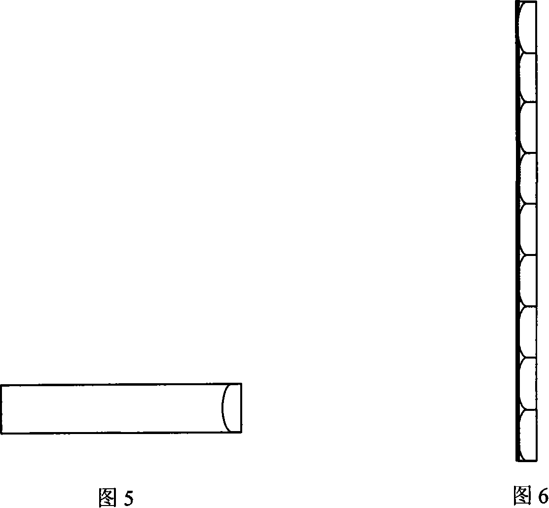
[0023] Example 2, the optical fibers with a length of 6-25000 mm can be directly stacked into the size required by the screen, and then the stacked optical fibers can be sliced ​​sequentially according to the required screen thickness by using thermal cutting wire, and the cut pieces can be flattened at 80-150 °C After that, the fiber optic micromirror composite layer can be made. For organic plastic optical fiber, a voltage regulator can be used to adjust the temperature of the cutting resistance wire. The higher the cutting temperature, the faster the cutting speed. The cutting temperature of organic plastic optical fiber is between 180 and 800°C. The temperature is 1200-1700°C. The screen manufactured by this method can omit the front light-transmitting layer of the screen, and has the characteristics of a transmission screen that forms images in the screen.

Embodiment 3

[0024] Embodiment 3: Engraving, die-casting or spraying the micromirror layer by means of laser engraving, die-casting and spraying according to the optical fiber stacking method. This method is suitable for manufacturing trapezoidal screens, that is, screens with small light-receiving surface and large imaging surface. The bottom of the engraved micromirror layer and the optical fiber contact layer are fully transparent, and the surroundings are coated with reflective film. This method can also be used to manufacture a screen that is imaged outside the back-end light-transmitting layer, that is, outside the screen, and can achieve very high screen gain.


PUM


Abstract

A high-gain transparent screen belongs to the field of transparent screen comprises a front-end transparent layer, a fiber transmission layer, a micro-lens layer and a back-end transparent layer through compounding. Wherein, the micro-lens layer is provided with a light spreading lens characterized by a horizontal spreading angle of 70 degrees to 120 degrees and a vertical spreading angle of 40 degrees to 80 degrees. The micro-lens is directly attached to a fiber head top or etched onto transparent materials of the back-end transparent layer. The fiber transmission layer is provided with even fiber diameters. The back-end transparent layer is black glass, a black real-time adhesive film, black anti-dazzle glass or a black real-time anti-dazzle adhesive film to enhance screen contrast and prevent screen reflection. The screen has the advantages of high gain, wide visual angle, lower cost, easy production of various screens with nonstandard size and seamless assembling.

Description

technical field [0001] The invention belongs to the field of transmission screens, and in particular provides a high-gain transmission screen, which can be widely used in the field of video rear projection screens. Background technique [0002] Transmissive screens are mainly used in projector rear projection mode. The image produced on the transmission screen by using the rear projection mode of the projector and the transmission screen can effectively overcome the interference of the natural light in front of the screen on the image and eliminate the screen image caused by the barrier between the front projector and the screen to the projector light. incomplete. Transmissive screens are very versatile. At present, the mainstream products of large-size transmissive screens are optical screens produced in Denmark with methyl methacrylate as the base material, a Fresnel lens on one side and a grating on the other. The screen gain is generally around 3.5; Small-size transmis...

Claims


Application Information

Patent Timeline
Patent Type & Authority Applications(China)
IPC IPC(8): G03B21/56G03B21/60G03B21/625
Inventor 白建荣樊胜利李洪林张永玲颜磊
Owner BEIJING FANGRUI BOSHI DIGITAL TECH
Why Eureka
Try Eureka